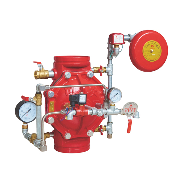
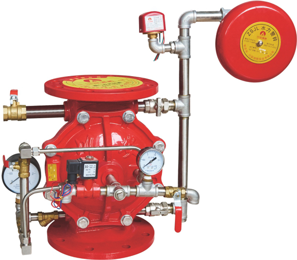
Grooved Deluge Valve
Victaulic-Compatible · DN80–DN200 · 1.6 MPa · Fast-Install · No Flange Bolting
Two-bolt clamp vs 8–12 flange bolts per joint — minutes instead of hours per valve station.
Groove dimensions per AWWA C606 — fits Victaulic, Anvil, Shurjoint and other major coupling brands.
No pipe alignment jig, no torque wrench specs, no gasket pre-fit — installer-friendly throughout.
Same full-bore EPDM diaphragm as flanged ZSFM — no hydraulic penalty for the connection method.
What "Grooved" Means & Why It Saves Install Time
The valve body has a precision-machined circumferential groove formed at each end. Instead of bolting two flange faces together with a gasket between them, two pipe ends are joined by sliding a two-piece coupling housing over the groove with a sealing gasket inside. The housing is closed with just two bolts, which clamp the housing into the grooves on both pipe ends, simultaneously sealing the gasket and mechanically locking the joint.
The mechanical advantages are immediate: no pipe alignment tooling required (the groove geometry self-centres the joint), no flange-bolt torque sequencing (just two bolts to tighten in alternating turns), no gasket pre-fit (the gasket is captive inside the coupling), and no torque calibration for differential bolt loading. The coupling can also accommodate small angular and axial movements — useful for buildings subject to thermal expansion or seismic micro-displacement.
The grooved end is dimensionally compatible with Victaulic, Anvil/Gruvlok, Shurjoint, and other major brand couplings per the AWWA C606 standard. Your specifying engineer's choice of coupling brand on the upstream pipework will fit this valve body without modification.
Complete Technical Specifications
Pressure Ratings & Body (ZSFM 80~200(G))
| Parameter | Value | Standard / Test |
|---|---|---|
| Nominal pressure | 1.6 MPa (PN16) | GB 5135.2 |
| Seal test pressure | 3.2 MPa | Hydrostatic, 10 min, zero leakage |
| Strength test pressure | 6.4 MPa | Hydrostatic, no deformation |
| Hydraulic resistance | < 0.08 MPa | At rated flow, full-bore waterway |
| Seal leakage | ≤ 0.1 L/min | Standby, diaphragm fully seated |
| Body material | Ductile iron | Higher tensile strength than grey cast iron |
| Diaphragm material | EPDM (fabric-reinforced) | Sprinkler & foam-water service |
| Internal trim | Brass / stainless steel | Corrosion-resistant standard |
| End connection | Grooved (Victaulic-compatible) | AWWA C606 groove dimensions |
| Couplings supplied | Optional — Victaulic-compatible 2-bolt clamp | Specify at order |
| Medium temperature | 4°C – 70°C | Ambient service |
| Suitable medium | Clean water · Foam solution (AFFF/AR-AFFF) | EPDM compatible |
Dimensions by Nominal Size
| Nominal Size | DN80 | DN100 | DN150 | DN200 |
|---|---|---|---|---|
| Overall height (mm) | 330 | 360 | 425 | 530 |
| Working pressure | 1.6 MPa (all sizes) | |||
| Seal test | 3.2 MPa | |||
| Strength test | 6.4 MPa | |||
| Hydraulic resistance | < 0.08 MPa | |||
Actuation Modes
| Mode | Trigger | Best For |
|---|---|---|
| Electric solenoid (standard) | Fire detection panel energises Ex / non-Ex solenoid trip valve | Most commercial & industrial deluge applications |
| Wet pilot | Pressurised water pilot line vented by pilot sprinkler | Hydraulic-only activation, no electrical reliance |
| Dry pilot (air/N₂) | Pressurised air pilot line vented by pilot sprinkler | Freezing environments, no-water pilot zones |
| Manual override — always available | Manual trip ball valve on valve trim | Maintenance, commissioning, emergency local trip |
Why Specify the ZSFM-G Grooved Deluge Valve
⏱️ Significant Project Schedule Savings
The grooved coupling installs in approximately 25% of the time required for a flanged joint of equivalent size. On a complete deluge valve station — with upstream isolation, valve, downstream isolation, drain, test connections, and trim — that's typically 6 to 10 joints per station. Specifying grooved across the entire station saves a typical contractor 1–2 working days per valve station vs flanged. On a multi-zone project with 4–6 valve stations, the cumulative saving runs to a full project week — which often translates directly to early commissioning bonus or avoided liquidated damages.
🔧 Installer-Friendly — Lower Skill Threshold
A flanged joint requires the installer to: stage the gasket, align both pipe ends, fit and crisscross-tighten 8–12 bolts to specified torque, and verify joint integrity with hydrostatic test before moving on. Each step has a specific failure mode — over-torqued bolts, off-centre gaskets, misaligned bolt holes. A grooved joint requires the installer to: slide the coupling housing over the joint, fit the captive gasket, tighten just two bolts. The skill threshold is dramatically lower and the failure modes much fewer — particularly valuable on projects where the contractor pool includes less experienced fitters.
🏗️ Same Operating Mechanism as Flanged ZSFM
The grooved end connection is the only difference between this valve and the flanged ZSFM. Internally, both use the same fabric-reinforced EPDM diaphragm, the same full-bore waterway, the same hydraulic resistance below 0.08 MPa, and the same 1-second valve open time. There is no hydraulic, mechanical, or operational compromise from choosing the grooved variant — it is simply the flanged valve with a faster-install end connection. Spare parts (diaphragm replacement kits, trim components) are interchangeable with the flanged version.
🔄 Allows for Thermal Expansion & Slight Misalignment
Unlike a rigid flange joint, a grooved coupling accommodates small angular and axial movements — typically up to 1–2° of angular flex and a few mm of axial displacement per joint. This is genuinely useful in tall building risers (thermal expansion), warehouses with seasonal floor settlement, and seismic-zone installations where rigid joints can crack. The flexibility doesn't come at the expense of pressure rating — the joint still holds 1.6 MPa working pressure with full safety margin.
Applications — Where Grooved Is the Right Specification
Commercial High-Rise Sprinkler Risers
Office towers, residential high-rises, hotels, and mixed-use developments where the entire firewater riser system is specified grooved throughout. Eliminates the flanged-to-grooved adapter at the valve station, simplifies the design and reduces joint count.
Healthcare & Hospital Facilities
Hospital wings, surgical centres, and medical office buildings where the deluge zones (e.g., MRI suites, helipads, kitchen exhaust) need to integrate with grooved firewater mains. Fast install also minimises disruption to occupied healthcare floors.
Warehouse & Logistics Centres
Large-area warehousing with foam-water deluge over flammable-liquid storage, conveyor protection, or high-rack storage. The cost-per-square-metre construction model makes install-time savings particularly valuable on these projects.
Aircraft Hangar Foam-Water Systems
Group II and III hangars with NFPA 409 foam-water deluge over the hangar floor. Grooved coupling speeds the install of the typically large-bore (DN150/DN200) supply pipework to the foam monitor or overhead spray network.
Retrofit & Tenant Improvement Projects
Adding deluge protection to an existing facility where downtime is expensive and the replacement window is limited. Grooved install minimises disruption and allows the system to be brought back online faster than a flanged equivalent.
Seismic Zone Installations
Buildings in seismic Zones 3 and 4 where rigid pipework joints risk crack propagation during an earthquake. Grooved couplings accommodate small displacements without compromising the pressure boundary — a recognised seismic-resilience feature in NFPA 13 / FM 1950.
Grooved vs Flanged — When to Specify Which
The choice between grooved and flanged is primarily a specification of the upstream and downstream pipework method. If the project pipework is grooved throughout, specify the grooved deluge valve to match. If the pipework is flanged or mixed, specify the flanged valve. Both have identical internals, identical performance, and identical pressure ratings.
The grooved version is typically at sizes DN80–DN200 only — for DN50/DN65 (small zones) or DN250/DN300/DN350 (large mains), specify the flanged version. Pricing between grooved and flanged is broadly similar; the value of grooved comes from project-schedule savings, not from the valve unit cost.
View Flanged Diaphragm Version →Frequently Asked Questions
Is the grooved deluge valve compatible with Victaulic couplings — or only with CA-FIRE's own brand?
The ZSFM-G groove dimensions follow the AWWA C606 standard, which is the same standard Victaulic, Anvil/Gruvlok, Shurjoint, and other major coupling manufacturers use. The valve body is dimensionally compatible with all AWWA C606-compliant couplings — including the standard Victaulic Style 005, 75, 77, and 177 couplings commonly specified on commercial fire sprinkler projects.
CA-FIRE can supply the valve with or without couplings included in the package. If your specifying engineer has a preferred brand (commonly Victaulic for international projects, or a regional brand for cost reasons), order the valve body alone and source couplings separately. If you'd prefer single-source supply, CA-FIRE can supply Victaulic-compatible couplings with the valve at competitive pricing.
Note: "Victaulic" is a trademark of Victaulic Company. CA-FIRE's product is described as Victaulic-compatible meaning it conforms to the same AWWA C606 standard and physically fits Victaulic couplings — it is not manufactured by Victaulic Company.
How does the install-time saving actually work out on a real project?
On a per-joint basis, a typical experienced fitter takes:
Flanged joint (DN150): ~90 minutes from "joint ready to install" to "leak-tested and signed off". This includes pipe alignment, gasket placement, bolt insertion, crisscross torquing to spec, and visual inspection.
Grooved joint (DN150): ~25 minutes for the same scope. Slide coupling housing over groove, fit captive gasket, hand-tighten two bolts in alternating turns, final wrench to spec, visual.
For a complete deluge valve station with 8 typical joints (upstream isolation, valve in/out, drain manifold, test, downstream isolation), the difference is ~12 hours flanged vs ~3.5 hours grooved — saving approximately one full working day per station. On a project with 4 valve stations, that's a full week of contractor time. The cost saving depends on local labour rates, but the schedule saving is consistent and often the more valuable consideration for time-driven projects.
Why is the grooved version only available in DN80–DN200 — what about smaller or larger sizes?
The DN80–DN200 range represents the commercial fire sprinkler sweet spot — these are the sizes used for the vast majority of building riser, zone supply, and standpipe deluge applications. The grooved coupling format is most economical and most widely standardised in this size range.
For DN50 and DN65 (small zone branches, foam concentrate lines, drain mains), grooved couplings are available but less common, and CA-FIRE typically supplies these as flanged. If your project specifically requires DN50 or DN65 grooved, contact us — we can arrange a custom-build but lead times are longer.
For DN250, DN300, and DN350 (large fire pump discharge mains, foam-water hangar deluge supply, transformer farm cooling), grooved couplings exist but the cost-benefit shifts as the coupling housings become very large and heavy. Flanged is the standard specification at these sizes, and CA-FIRE manufactures the flanged ZSFM up to DN350.
Why ductile iron rather than cast iron for the grooved version?
The grooved end requires a circumferential machined groove in the valve body, which creates a localised stress concentration at the groove root. Standard grey cast iron has lower tensile strength and lower elongation than ductile iron — meaning a grey cast iron groove can be more prone to crack initiation under cyclic pressure, particularly if there's any installation stress on the joint.
Ductile iron (also called nodular iron or spheroidal graphite iron) has approximately 2× the tensile strength and 5–10× the elongation of grey cast iron. The graphite is in spherical (nodular) form rather than flake form, eliminating the stress-concentration effect of flake graphite. This makes ductile iron the correct material for any grooved valve body — the additional cost over grey cast iron is modest (~10–15%), and the safety and durability margin is substantially better.
The flanged ZSFM uses standard grey cast iron because the flange face has uniform stress distribution and no machined notch.
Can the grooved deluge valve be used with foam-water systems?
Yes — the ZSFM-G is fully compatible with AFFF and AR-AFFF foam solutions at 3% and 6% application rates. The EPDM diaphragm, the brass/stainless trim, and the ductile iron body with epoxy coating all tolerate foam concentrate exposure without degradation. The grooved coupling gasket itself is also EPDM and is foam-compatible.
Common foam-water applications using the grooved deluge valve: aircraft hangar floor deluge (NFPA 409), helideck foam-water (NFPA 418), flammable-liquid warehouse foam-water spray, and vehicle workshop foam-water systems. For the upstream foam concentrate proportioning, see CA-FIRE's foam bladder tank product line — designed to integrate seamlessly with the deluge valve station downstream.
What information do you need to prepare a quotation for a grooved deluge valve?
To prepare an accurate quotation, please provide: (1) nominal size (DN80, DN100, DN150, or DN200) and quantity per size; (2) actuation mode preference — electric solenoid (standard), wet pilot, dry pilot, or specified at site; (3) whether couplings should be included in the package — Victaulic-compatible 2-bolt clamps from CA-FIRE, or valve body only with the contractor sourcing couplings separately; (4) upstream pipework type (carbon steel grooved, ductile iron grooved, or stainless grooved) — affects coupling selection; (5) any certification scope beyond the standard GB 5135.2 — UL-listed and FM-approved variants are available on specification; (6) installation location (indoor / outdoor / sheltered / freezing) — affects trim and accessory specification.
Contact sales@ca-fire.com or WhatsApp +86 18150362095. Quotations typically turn around in 1–2 business days for standard GB-certified scope; 3–5 business days for UL/FM-listed scope.
Related Deluge Valve Products
Further Reading — Grooved & Sprinkler System Resources
Complete classification framework for all 7 deluge valve types — when to specify diaphragm vs piston, flanged vs grooved, cast iron vs stainless, and which is right for your project. Read the types guide →
Step-by-step explanation of standby, trip, discharge and reset for the diaphragm deluge valve mechanism — same operation applies to the grooved version. Read the operation guide →
Annotated breakdown of every component in a complete deluge valve station, covering both flanged and grooved configurations with their respective trim. Read the components guide →
Step-by-step install procedure with NFPA 13 acceptance test walkthrough and downloadable checklist — covers flanged-to-grooved differences. Read the installation guide →
Get a Quote — Grooved Deluge Valve (ZSFM-G Series)
DN80–DN200 · 1.6 MPa · Ductile Iron · Victaulic-Compatible AWWA C606 · EPDM Diaphragm
Commercial High-Rise · Healthcare · Warehouse · Hangar · Fast-Track Project Schedules · Worldwide Export