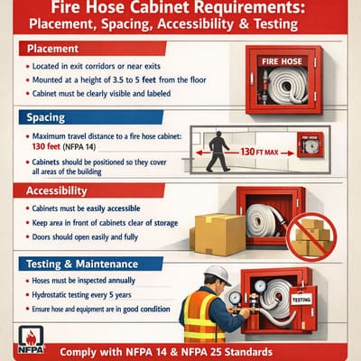
NFPA Fire Hose Cabinet Requirements: Placement, Spacing, Accessibility & Testing
NFPA 14 is the primary standard governing fire hose cabinets in the United States and many export markets. The core requirements: hose stations must be located on every floor of a building with a standpipe system, positioned so that every point on the floor can be reached by a 30-foot (9 m) stream from the nozzle plus the hose length, with the valve outlet between 3 and 5 feet (36–60 inches) above finished floor. Cabinets must be identified with permanent signage, protected from physical damage, accessible without keys or special tools, and visually inspected monthly with operational testing annually under NFPA 25.
This guide consolidates the specific requirements from five NFPA standards (14, 10, 25, 1 and 101) that affect fire hose cabinet specification, placement, accessibility and ongoing compliance — organised by topic so you can find the rule that applies to your project without reading five separate standards.
- Which NFPA standards apply to fire hose cabinets
- Where standpipe hose outlets must be located
- Coverage and spacing requirements
- Valve outlet height and orientation
- Cabinet accessibility and obstruction rules
- Signage and identification requirements
- Inspection, testing and maintenance schedule
- Documentation and record-keeping
- International equivalents (non-U.S. projects)
- Frequently asked questions
Which NFPA Standards Apply to Fire Hose Cabinets
A fire hose cabinet sits at the intersection of multiple NFPA standards, each governing a different aspect of the system. No single standard covers every requirement. The five relevant standards and their roles:
| Standard | Full Title | What It Governs |
|---|---|---|
| NFPA 14 | Standard for Installation of Standpipe and Hose Systems | System design, placement, pipe sizing, flow/pressure, hose station location |
| NFPA 10 | Standard for Portable Fire Extinguishers | Extinguisher placement, mounting height, maintenance (applies when extinguisher is in cabinet) |
| NFPA 25 | Standard for Inspection, Testing and Maintenance of Water-Based Fire Protection Systems | Monthly visual inspection, annual operational testing, 5-year flow test, hose replacement |
| NFPA 1 | Fire Code | When standpipe systems are required, by building height, area and occupancy classification |
| NFPA 101 | Life Safety Code | Accessibility of fire protection equipment in means of egress, corridor width around cabinets |
In practice, NFPA 14 drives most decisions about where and how to install hose cabinets. NFPA 25 drives ongoing maintenance after the building is occupied. NFPA 10 adds requirements only when the cabinet includes a portable extinguisher. NFPA 1 and 101 set the trigger — when a building needs a standpipe system at all — but once the trigger is met, NFPA 14 takes over.
Outside the United States, equivalent standards include the International Fire Code (IFC), BS 9990 in the United Kingdom, EN 671 in Europe, and GB 16280 in China. The rest of this guide cites NFPA numbers specifically, but the underlying engineering requirements are broadly similar across all major fire codes. For your specific project, always verify against the standard adopted by the local Authority Having Jurisdiction (AHJ).
Where Standpipe Hose Outlets Must Be Located
NFPA 14 specifies where hose outlets — and by extension, the cabinets that house them — must be placed. The standard does not use the language “one per floor” as a blanket rule; instead it specifies locations based on stairway proximity and travel distance. The two primary location requirements:
NFPA 14 requires a hose outlet at the intermediate landing between floors in each required stairway, or at the main floor landing adjacent to the standpipe riser. The outlet must be positioned so that it is accessible from the stairway without leaving the fire-rated stair enclosure. This is the rule that puts hose outlets in every stairwell at every floor.
On floors where Class II or Class III hose stations are required for occupant use, additional outlets may be placed along corridors so that every point on the floor is within reach of a hose stream (typically within 30 feet / 9 m of the nozzle tip plus the full hose length from the nearest outlet). This coverage rule may result in multiple outlets per floor on large floor plates.
Additional specific locations
Beyond the stairway and corridor rules, NFPA 14 and the IFC require hose outlets in several specific locations regardless of general coverage calculations:
- Roof access — an outlet at the highest landing of each required stairway that accesses the roof.
- Below-grade levels — an outlet on every level that is more than one storey below grade and accessible to the fire department.
- Mechanical equipment rooms — outlets are sometimes required in large mechanical rooms that are remote from corridor hose stations, depending on local AHJ interpretation.
- Covered mall buildings — specific outlet placement rules apply in covered mall occupancies under the IFC, often requiring outlets both in the mall corridors and within individual tenant spaces.
- Stages and platforms — assembly occupancies with stages larger than 1,000 sq ft (93 m²) require hose outlets on each side of the stage.
Coverage and Spacing Requirements
The coverage rule is one of the most frequently misunderstood aspects of NFPA 14. The standard does not specify a fixed distance between cabinets (like “one every 30 metres”). Instead, it specifies a coverage performance criterion: every point on the floor must be reachable by a hose stream from the nearest outlet.
The calculation for Class II and Class III occupant hose stations works as follows:
- Hose length — typically 30 metres (100 feet) for a standard occupant hose. This is measured along the walking path from the cabinet to the point of use, not as a straight line through walls.
- Nozzle reach — typically 30 feet (9 metres) of effective stream from the nozzle tip to the fire.
- Total reach — hose length plus nozzle reach. For a 100-foot hose, total reach is approximately 130 feet (40 metres) from the cabinet. Every point on the floor must be within this radius of at least one cabinet.
For Class I fire department hose stations, the coverage calculation uses the fire department’s own hose (which they bring from the truck), so the cabinet spacing is driven by the stairway-landing rule rather than a floor-coverage radius. In practice this usually results in one outlet per stairway per floor.
On large floor plates — 2,000 m² or more — the coverage calculation often results in more than one cabinet per floor. A 50-metre by 40-metre warehouse floor, for example, might need two or three cabinets to ensure every corner is within 40 metres of hose-plus-nozzle reach. The fire protection engineer runs a coverage map as part of the system design; the locations appear on the fire protection drawings as part of the submittal package.
Valve Outlet Height and Orientation
NFPA 14 specifies the centerline of the hose valve outlet between 3 feet and 5 feet (36 to 60 inches / 914 to 1524 mm) above the finished floor. This range is intentionally wide — it allows the designer to choose a height that satisfies the additional constraints imposed by ADA accessibility rules, NFPA 10 extinguisher mounting height (if the cabinet includes an extinguisher), and the specific cabinet configuration.
In most practical installations, the valve centerline ends up at approximately 48 inches (1219 mm) above finished floor. This position balances NFPA 14’s range with the ADA forward-reach rule (operable parts at or below 48 inches) and places the valve at a comfortable operating height for both a standing adult and a wheelchair user. For a complete breakdown of how four different standards interact on mounting height, see our fire cabinet mounting height guide.
Valve orientation
The angle valve outlet should face toward the operator — horizontally, pointing out from the wall when the cabinet door is open. The standard does not specify left-hand versus right-hand orientation, but convention is to position the valve so the handle is accessible from the natural approach direction. In corridor cabinets this typically means the handle faces the center of the corridor; in stairway cabinets it faces the landing.
Cabinet Accessibility and Obstruction Rules
NFPA 14, NFPA 1 and NFPA 101 (Life Safety Code) all contribute to the accessibility requirements for fire hose cabinets. The combined rules amount to three principles:
Principle 1 — No locks that delay access
Fire hose cabinets must be accessible without keys, special tools or complicated procedures. A simple door handle, push latch, or break-glass front are all acceptable. Padlocks, key locks and electronic access controls that would delay an untrained user by even a few seconds are generally not permitted on Class II and Class III occupant-use cabinets. Class I fire department cabinets may use a department-standard lock (such as a Knox-Box or FD key) because the user is a trained professional with the key, but even then the local AHJ must approve the lock type.
Principle 2 — No physical obstructions
The path from the corridor to the cabinet must be clear and unobstructed at all times. This means no furniture, no storage, no display racks, no stacked boxes, and no equipment placed in front of or beside the cabinet that would prevent the door from opening fully or prevent an operator from pulling the hose straight out. NFPA 1 requires a minimum of 36 inches (914 mm) of clear space in front of the cabinet — enough for a person to stand, open the door, and pull hose or an extinguisher without interference.
Principle 3 — Do not reduce egress corridor width
NFPA 101 requires that fire protection equipment mounted on corridor walls must not reduce the required egress width of the corridor below the code minimum (typically 44 inches / 1118 mm for commercial occupancies, 48 inches / 1219 mm for healthcare). A surface-mount cabinet projecting 240 mm (9.5 inches) from the wall reduces effective corridor width by almost 10 inches — on a narrow corridor this may violate the minimum width. This is a second reason (beyond ADA protruding objects) to specify recessed cabinets in finished corridors.
Signage and Identification Requirements
NFPA 14 and NFPA 1 both require that hose stations be clearly identified and visible. The specific requirements:
- Permanent signage on the cabinet door — text reading “FIRE HOSE” or equivalent in letters large enough to be read from a distance of 30 feet (9 m) under normal lighting conditions. Red letters on a white background, or white letters on a red background, are both acceptable.
- Valve class identification — on Class III combined cabinets, each valve must be labelled to distinguish the 2.5-inch fire department connection from the 1.5-inch occupant hose. Labels reading “2½ in. Fire Department” and “1½ in. Occupant Hose” are typical.
- Riser identification — on buildings with multiple standpipe risers, the cabinet signage should include the riser designation (e.g. “Riser A,” “Riser B”) so firefighters can communicate valve positions during operations.
- Operating instructions — Class II and Class III occupant hose stations should have printed or engraved operating instructions mounted inside the cabinet door showing the deployment sequence in plain language. Multi-language instructions are recommended for mixed-language occupancies.
- Floor identification — in buildings taller than four storeys, each hose station should include a floor-level identifier visible when the cabinet is opened, so responding firefighters can confirm they are on the correct floor.
Signage that is faded, peeling, painted over or removed during renovation must be replaced during the next scheduled inspection. Signage failures are among the most common findings during fire audits. For details on the physical components that should be visible inside the cabinet, see our complete contents guide.
Inspection, Testing and Maintenance Schedule
NFPA 25 is the standard that governs ongoing inspection and testing after the system is installed and the building is occupied. The schedule below is a summary of the NFPA 25 requirements that apply specifically to fire hose stations and their cabinets. A more detailed inspection procedure is available in our monthly inspection checklist.
| Frequency | Task | Standard | What to Check |
|---|---|---|---|
| Monthly | Visual inspection | NFPA 25 | Tamper seal, signage, cabinet condition, no obstruction, hose condition (no mould/stiffness), nozzle present, extinguisher gauge |
| Annually | Operational test | NFPA 25 | Open valve to verify water flow, check for leaks, verify nozzle pattern, re-fold hose on rack |
| Annually | Extinguisher service | NFPA 10 | Professional inspection, verify weight, check pressure, replace tamper seal on extinguisher |
| Every 3 years | Hose rack deployment test | NFPA 25 | Fully deploy hose from rack, verify tangle-free deployment, re-fold and re-rack |
| Every 5 years | Full flow test + hose hydrostatic test | NFPA 25 | Full system flow test at design pressure, hydrostatic test of individual hose sections, replace any failed hose |
| Every 6 or 12 years | Extinguisher internal maintenance | NFPA 10 | Internal examination, recharge, hydrotest of cylinder (interval depends on extinguisher type) |
The most frequently missed task is the monthly visual inspection — many buildings skip it because “nothing ever changes.” But it is during these monthly walks that common failures like missing nozzles, broken tamper seals, depressurised extinguishers and stored personal items are caught before they become audit findings.
Documentation and Record-Keeping
NFPA 25 requires that all inspection, testing and maintenance activities be documented in writing and retained for at least one year (many AHJs require longer retention — often 3 to 5 years). The documentation must include:
- Date of each inspection or test and the name of the qualified inspector.
- Findings — specifically, any deficiencies noted and the corrective actions taken or planned.
- Test results — flow rates and pressures for annual and 5-year tests, hydrostatic test results for hose.
- Equipment identification — which cabinet/outlet was tested, identified by floor, riser designation and location.
- Next scheduled date for the next test cycle.
Most commercial buildings today use digital inspection management systems (cloud-based CMMS or fire inspection apps) rather than paper logs. The format does not matter to the standard — paper, spreadsheet or software are all acceptable — as long as the records exist, are complete, and are available for review by the AHJ during audits. Missing inspection records is one of the most common findings during fire safety audits and can result in the building being placed on a corrective action plan.
International Equivalents (Non-U.S. Projects)
For projects outside the United States, the NFPA 14 requirements described in this guide have close equivalents in other national and regional fire codes. The specific numbers may differ, but the engineering logic is the same: every floor needs a water outlet, every outlet must be accessible and clearly identified, and the system must be tested on a regular schedule.
| Region | Equivalent Standard | Key Difference from NFPA 14 |
|---|---|---|
| United Kingdom | BS 9990 / BS 5306 | Uses “wet riser” and “dry riser” terminology; fire service inlet (FSI) replaces FDC |
| European Union | EN 671-1 / EN 671-2 | EN 671-1 covers hose reels; EN 671-2 covers lay-flat hose. Different hose diameter standards (DN 19/25/33). |
| China | GB 16280 / GB 50974 | GB 16280 is the fire hose cabinet box standard; GB 50974 governs building water supply systems including standpipe. Uses “消火栓箱” terminology. |
| Middle East / GCC | NFPA 14 (adopted) | Most GCC jurisdictions adopt NFPA directly; UAE Civil Defence has additional local supplements. |
| Southeast Asia | Mixed (NFPA / BS / local) | Singapore uses SS CP 52 (based on British standard); Philippines uses NFPA directly; other countries vary. |
CA-FIRE manufactures cabinets to serve all these markets. The SG24 fire hose cabinet range is designed to the principles of both NFPA 14 and GB 16280, and has been installed in projects across all of the regions listed above. For projects in jurisdictions that adopt a non-NFPA code, confirm the specific cabinet requirements with the local fire authority before ordering.
Frequently Asked Questions
Does NFPA 14 apply to the cabinet itself or just the standpipe system?
NFPA 14 governs the standpipe system including hose outlets, valves, piping and flow requirements. It does not directly certify or test the enclosure (the cabinet body) — the cabinet is a piece of hardware that houses the outlet. What NFPA 14 does require is that the outlet be accessible, identified and protected, which indirectly determines the cabinet location, signage, accessibility and mounting configuration. The cabinet body itself is typically manufactured to ISO 9001 quality standards rather than a specific NFPA product certification.
How high should the hose valve be above the floor?
NFPA 14 specifies the centerline of the hose valve outlet between 3 and 5 feet (36 to 60 inches) above the finished floor. In most practical installations the valve centerline ends up at approximately 48 inches, which also satisfies the ADA forward-reach rule. For a comprehensive breakdown including the ADA protruding objects rule and OSHA, see the mounting height guide.
How many fire hose cabinets per floor does NFPA require?
NFPA 14 does not specify a fixed number per floor. Instead it uses a coverage performance criterion: every point on the floor must be reachable by a hose stream from the nearest outlet (typically 30 feet nozzle reach plus the full hose length). For small floors one cabinet may suffice; for large floor plates (2,000 m² or more) multiple cabinets may be needed. Additionally, outlets are required at each stairway landing. The fire protection engineer calculates the exact number as part of the system design.
How often must fire hose cabinets be inspected?
NFPA 25 requires monthly visual inspection (check seal, signage, no obstruction, visual hose and nozzle condition), annual operational testing (open the valve, verify water flow, re-fold hose), a deployment test every 3 years, and a full hydrostatic flow test every 5 years. Portable extinguishers inside the cabinet have their own separate schedule under NFPA 10 — annual professional service plus internal recharge every 6 or 12 years depending on extinguisher type.
Can a fire hose cabinet door be locked?
Class II and Class III occupant-use cabinets generally cannot be locked because the user may be an untrained building occupant who does not carry a key. Simple push latches, magnetic catches, and break-glass fronts are all acceptable. Class I fire department cabinets may use a department-standard lock (such as Knox-Box) with AHJ approval, since the user is a trained professional. Any lock that would delay access by even a few seconds is typically rejected by fire inspectors.
What signage is required on a fire hose cabinet?
At minimum: a permanent “FIRE HOSE” label on the exterior door readable from 30 feet, valve class identification labels inside (especially for Class III with two valve sizes), operating instructions inside the door for occupant-use cabinets, riser designation if the building has multiple risers, and a floor identification marker in buildings taller than four storeys. Inspection records and the current inspection tag should also be accessible inside or adjacent to the cabinet.
Does NFPA 14 apply outside the United States?
NFPA 14 is a U.S. standard but is adopted or referenced in fire codes across much of the world, including most of the Middle East and GCC countries, parts of Southeast Asia, parts of Latin America, and Canada. Other regions use equivalent standards with similar technical requirements: BS 9990 in the United Kingdom, EN 671 in Europe, GB 16280 and GB 50974 in China. The underlying engineering principles — outlet location, coverage, testing — are the same across all major standards.
How much clear space must be maintained in front of the cabinet?
NFPA 1 requires a minimum of 36 inches (914 mm) of clear space in front of the cabinet at all times — enough for one person to stand, fully open the door, and pull the hose or extinguisher without interference. No furniture, storage, display racks or stacked materials may be placed within this clearance zone. Obstructed cabinets are one of the most common findings during fire safety audits and result in corrective action orders.
Keep Reading
▸ Fire Cabinet Mounting Height: ADA & NFPA Rules — Four-standard mounting height comparison
▸ NFPA 14 Class I, II & III Explained — Standpipe class system deep-dive
▸ Monthly Inspection Checklist — Practical step-by-step inspection procedure
▸ What’s Inside a Fire Hose Cabinet — Complete equipment inventory
▸ Fire Hose Cabinet Dimensions Guide — SG24 size and rough opening tables
▸ Recessed vs Surface Mount Comparison — Which mounting type for your corridors
Need NFPA 14-Compliant Fire Hose Cabinets?
CA-FIRE manufactures the SG24 fire hose cabinet range to the principles of NFPA 14 and GB 16280. Available in tempered glass, stainless steel and recessed flush-mount configurations, four standard sizes from 800 to 2000 mm. Factory direct from Fujian, China. Free CAD and Revit files for every size.