|
Technical Guide
March 2026 · 10 min read
What Is a Gate Valve? How It Works, Types, Parts & Applications
A gate valve is the standard isolation valve for fire protection systems, water distribution mains and industrial pipework. This guide covers everything you need to know: what a gate valve is, how it works, its main parts and functions, the different types available, and where gate valves are specified.
What Is a Gate Valve?
A gate valve is a linear-motion isolation valve that controls flow by raising or lowering a flat or wedge-shaped disc — the "gate" — perpendicular to the direction of flow. When the gate is fully raised, the full pipe bore is unobstructed and water flows through with essentially zero pressure drop. When the gate is fully lowered, it presses against two valve seats and seals the pipeline completely.
Gate valves are designed for on/off isolation only. They should always be operated either fully open or fully closed — never partially open for flow regulation. At partial-open positions, the gate disc vibrates in the flow stream and rapidly erodes the seating faces, causing the valve to leak even when closed.
|
Full-Bore
Flow path
|
8–16
Turns open→close
|
PN16
Working pressure
|
DN50–400
Size range
|
How Does a Gate Valve Work?
A gate valve works by converting the rotational motion of a handwheel into the linear vertical movement of a gate disc via a threaded stem. The operating sequence is straightforward:
|
1
|
Handwheel rotation
Turning the handwheel clockwise rotates the stem. The threaded connection between stem and yoke converts rotation into linear motion — the stem and attached gate disc move downward.
|
|
2
|
Gate enters the flow path
As the gate disc descends, it enters the valve body and begins to obstruct the bore. Water pressure pushes against the gate disc as it crosses the pipe interior.
|
|
3
|
Gate seats and seals
The wedge-shaped gate disc presses firmly against two valve seats machined into the valve body. On resilient wedge valves, the EPDM rubber encapsulation deforms slightly to create a zero-leak seal against both seats simultaneously.
|
|
↑
|
Opening: reverse the process
Turning the handwheel anticlockwise raises the gate completely out of the flow path into the bonnet. The full pipe bore is restored and flow passes through with negligible restriction.
|
Why multiple turns? Gate valves require 8–16 full turns to open or close fully. This is intentional — the slow operation protects against water hammer (pressure surge) that would occur if a large-bore pipeline were opened or closed rapidly.
Gate Valve Parts & Functions
A gate valve consists of several key components. Understanding each part helps with specification, maintenance and troubleshooting.
| Part |
Description |
Function |
| Body |
Ductile iron, FBE coated |
Main pressure-containing shell. Houses the gate, seats and flow ports. End connections (flanged or grooved) connect to the pipeline. |
| Bonnet |
Bolted to valve body |
Encloses the upper part of the valve and guides the stem. Contains the packing chamber that seals around the stem to prevent leakage. |
| Gate (Wedge) |
Solid, flexible or resilient wedge |
The closure element. Moves up and down perpendicular to flow. The wedge shape allows it to wedge tightly against both seats when closed. |
| Seats |
Two seats, one each side of bore |
The sealing surfaces that the gate disc presses against when closed. On resilient wedge valves the gate EPDM rubber contacts the seats directly for zero-leak shutoff. |
| Stem |
Rising (OS&Y) or non-rising (NRS) |
Connects the handwheel to the gate disc. Converts handwheel rotation into linear movement of the gate. On OS&Y valves the stem rises visibly when opening. |
| Yoke |
OS&Y valves only |
The external frame that supports the stem nut (yoke nut). The stem threads through the yoke nut — as the nut is turned by the handwheel, the stem rises or falls. |
| Handwheel |
Cast iron or ductile iron |
The operating element. Turned by hand (or wrench for larger sizes). Clockwise = close; anticlockwise = open on most gate valves. |
| Packing / Gland |
Gland packing in bonnet |
Seals around the stem where it exits the bonnet to prevent water leakage. Can be tightened or replaced in-line without removing the valve from the pipeline. |
| Position Indicator |
Rising stem or dial indicator |
Shows whether the valve is open or closed. Critical for fire protection systems — NFPA 13 requires clear position indication on all sprinkler supply isolation valves. |
Types of Gate Valve
Gate valves are classified by stem type, end connection and gate disc type. For fire protection, the stem type and supervisory capability are the most important selection criteria.
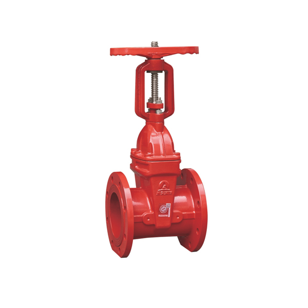
1. OS&Y Gate Valve — Outside Screw & Yoke (Rising Stem)
|
The OS&Y gate valve has an externally threaded stem that rises above the handwheel as the valve opens. This rising stem provides immediate, unambiguous visual position indication visible from across a room — stem extended means open, stem flush means closed. No closer inspection is needed.
OS&Y gate valves are the primary NFPA 13 specified valve type for fire sprinkler supply mains. They are also the most common valve type in fire pump rooms. Available in DN50–DN400 with flanged ends.
|
Key Specs
✓ Rising stem — visual from distance
✓ NFPA 13 compliant
✓ Flanged DN50–DN400 · PN16
✓ Accepts tamper switch
|
→ View CA-FIRE OS&Y Gate Valve
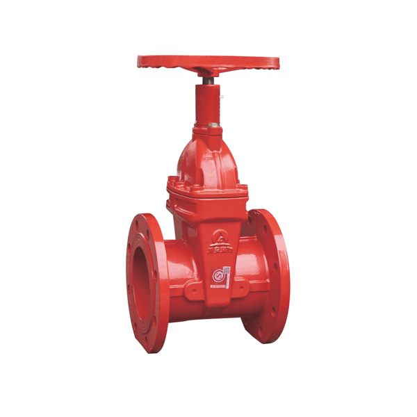
2. NRS Gate Valve — Non-Rising Stem
|
The NRS gate valve has a stem that rotates in place inside the valve body without rising — the threads are internal. Position is shown by a dial indicator mounted on the handwheel hub, which rotates to show "Open" or "Closed" as the handwheel is turned.
Because no headroom is needed above the handwheel, NRS gate valves are the standard choice for underground, pit-mounted or ceiling-level installations. Also widely used on buried water mains. Available DN50–DN400 with flanged ends.
|
Key Specs
✓ Compact — no stem extension
✓ Dial position indicator
✓ Flanged DN50–DN400 · PN16
✓ NFPA 13 compliant
|
→ View CA-FIRE NRS Gate Valve
3. Grooved Gate Valve — Victaulic-Compatible
|
Grooved gate valves replace flanged end connections with circumferential grooves machined to the ANSI/AWWA C606 standard — the same groove profile used by Victaulic and all major grooved coupling manufacturers. Couplings clamp over the grooves to join the valve to the pipeline.
Grooved connection eliminates the need for flange bolting and gaskets, significantly reducing installation time. The grooved gate valve has a non-rising stem with dial indicator and is available in DN50–DN300.
|
Key Specs
✓ AWWA C606 grooved ends
✓ Victaulic compatible
✓ DN50–DN300 · PN16
✓ NRS dial indicator
|
→ View CA-FIRE Grooved Gate Valve
4. Gate Valve with Tamper Switch
|
A gate valve with an integral supervisory tamper switch sends an electrical signal to the fire alarm control panel (FACP) within 2 turns of the handwheel if the valve is moved from its fully-open position. This satisfies the NFPA 72 supervisory monitoring requirement for fire sprinkler control valves.
The tamper switch is an SPDT (single-pole double-throw) device rated for 24VDC or 120VAC, with IP54 protection. Available with grooved ends, DN50–DN300.
|
Key Specs
✓ SPDT tamper switch
✓ NFPA 72 supervisory
✓ 24VDC / 120VAC · IP54
✓ Grooved DN50–DN300
|
→ View CA-FIRE Tamper Switch Gate Valve
5. Resilient Wedge Gate Valve
|
A resilient wedge gate valve uses a gate disc that is completely encapsulated in EPDM rubber. The rubber deforms slightly as the gate seats, conforming to any minor imperfections in the seat faces and creating a reliable zero-leak seal — even after years of infrequent operation.
This design is superior to the traditional solid wedge gate valve in corrosion resistance and sealing reliability. The EPDM-encapsulated gate does not corrode even in aggressive water, making it the preferred choice for fire protection and water distribution.
|
Key Specs
✓ EPDM-encapsulated wedge
✓ Zero-leak shutoff
✓ Superior corrosion resistance
✓ Grooved DN50–DN300
|
→ View CA-FIRE Resilient Wedge Gate Valve
Gate Valve Wedge Types
The gate disc (wedge) design significantly affects sealing performance, operating torque and long-term reliability. Three wedge types are in common use:
| Wedge Type |
Description |
Best For |
| Resilient Wedge |
Ductile iron core fully encapsulated in EPDM rubber. Rubber deforms to seal against both seats. |
Fire protection, water distribution. Best sealing, best corrosion resistance. ✅ Recommended |
| Solid Wedge |
Single rigid metal wedge. Simple, strong. Both seat angles must be precisely matched. |
Steam, high temperature, high pressure. Metal-seated valves for aggressive media. |
| Flexible Wedge |
Single wedge with a circumferential groove that allows slight flexing to compensate for seat misalignment. |
Steam and thermal cycling applications where thermal expansion causes seat misalignment. Power station valves. |
Gate Valve Applications
🔥 Fire Protection Systems
OS&Y and NRS gate valves on sprinkler supply mains (NFPA 13). Tamper switch valves for FACP supervisory monitoring. Signal gate valves for BMS integration. Fire pump suction and discharge isolation.
|
💧 Water Distribution
Municipal water supply mains. Zone isolation valves. Connection points between sections of the distribution network. Underground service connection valves (NRS type).
|
🏭 Industrial Process
Process pipework isolation in chemical plants, refineries and power stations. Supply main shutoffs where zero headloss is critical. Large-bore isolation valves on water treatment plant inlet/outlet mains.
|
🏗 Building Services
Sprinkler zone control valves. Main water supply isolation to buildings. Plant room isolation valves for fire pumps, heat exchangers and cooling towers. High-rise riser isolation.
|
Frequently Asked Questions
Q1 — What is a gate valve?
A gate valve is a linear-motion isolation valve that controls flow by raising or lowering a wedge-shaped disc across the pipe bore. When fully raised the bore is unobstructed — negligible pressure drop. When fully lowered it seals against two seats and stops flow completely. Gate valves are designed for on/off use only, not throttling.
Q2 — How does a gate valve work?
Turning the handwheel rotates the stem, which converts rotation to linear movement of the gate disc via threads. Clockwise turns lower the gate into the flow path and seal it against the two valve seats. Anticlockwise turns raise the gate fully into the bonnet, unobstructing the bore. Most gate valves require 8–16 full turns to fully open or close.
Q3 — What are the main types of gate valve?
The main types are: OS&Y (rising stem, visual position indication, NFPA 13 standard for sprinkler mains), NRS (non-rising stem with dial indicator, for confined spaces), grooved-end gate valve (Victaulic-compatible, fast installation), gate valve with tamper switch (supervisory monitoring, NFPA 72), resilient wedge gate valve (EPDM-encapsulated, zero-leak), and signal gate valve (dual micro-switch for BMS).
Q4 — What is a gate valve used for?
Gate valves are used for isolation — fully opening or fully closing a pipeline. Main applications: fire sprinkler supply main isolation (NFPA 13 requirement), water distribution mains, fire pump connections, industrial process pipework isolation. Gate valves are not used for flow regulation — that requires a globe valve or control valve.
Q5 — What is the difference between a rising stem and non-rising stem gate valve?
A rising stem (OS&Y) gate valve has a stem that extends upward as it opens — stem extended = open, stem retracted = closed. Visible from across a room. Needs headroom above the handwheel. An NRS gate valve stem rotates in place without rising — position shown by a dial indicator. Compact, suited for underground or ceiling-level installation. Both types are NFPA 13 compliant. See OS&Y and NRS gate valves.
Related Articles
|
Gate Valve vs Ball Valve
Quarter-turn vs multi-turn — and why fire systems need gate valves.
Read article →
|
Gate Valve vs Globe Valve
Isolation vs flow control — pressure drop and specification explained.
Read article →
|
|