
Deluge Valve Components & Trim — Complete Parts Guide
By the CA-FIRE engineering team · 14 min read · Updated 2026
A complete deluge valve assembly is more than just the alarm valve body — it’s an integrated station of 17 individual components working together to keep firewater under control during standby and release it instantly when fire is detected. Misidentifying a component or specifying the wrong replacement part is one of the most common reasons fire suppression systems fail their NFPA 25 trip tests.
This guide walks through every component on a CA-FIRE ZSFM deluge alarm valve assembly — what each part does, what its normal standby state should be, and the typical fault modes. The information is drawn directly from CA-FIRE’s factory operation manual, the same document supplied with every ZSFM-series deluge valve shipped from our Fujian facility.
Key Takeaways
- A complete deluge valve station has 17 individual components grouped into 5 functional categories.
- The diaphragm chamber is the heart of the valve — its pressure must equal supply-side pressure during standby.
- Two valves (alarm ball valve, both butterfly valves) are normally open; six valves are normally closed.
- The supply-side pressure gauge should read 0.2–1.6 MPa depending on system design pressure.
- Annual NFPA 25 trip-testing verifies every component operates correctly — components rarely fail in isolation.
📐 Reference Diagram — All 17 Components Labelled
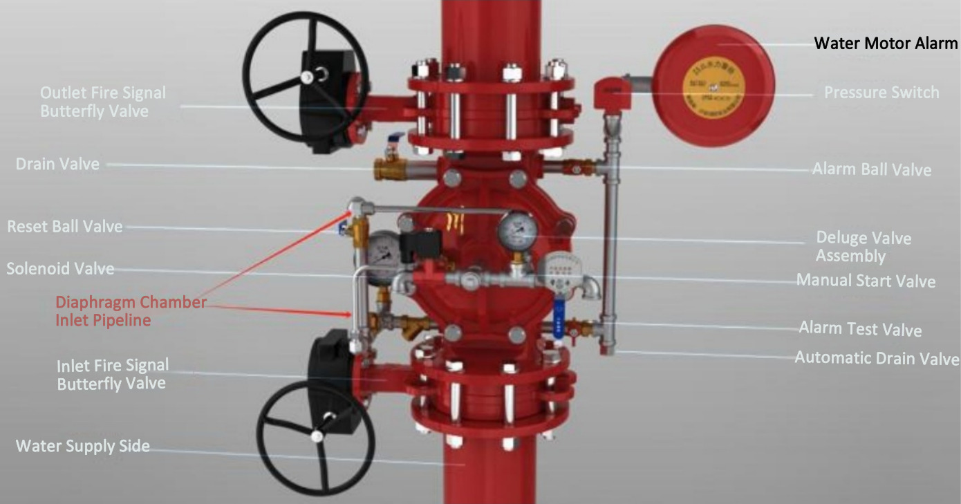
CA-FIRE ZSFM deluge alarm valve assembly — full component layout. Refer to this diagram throughout the guide.
Category 1 — The Main Deluge Alarm Valve
1. Deluge Alarm Valve Assembly
The main system control valve and the centrepiece of the entire assembly. The valve body houses the EPDM diaphragm (or stainless steel piston in high-pressure variants), the diaphragm chamber, and the seat against which the diaphragm seals. During standby it is fully closed with tight valve sealing and zero leakage. When tripped, the diaphragm lifts off the seat and full-bore water flow connects the supply side to the system piping network.
Standby Condition
Fully closed · Tight valve sealing · No leakage past the seat or from the body
For the technical specifications and pressure ratings of the CA-FIRE ZSFM main valve body, see the diaphragm deluge valve product page.
Category 2 — Isolation Butterfly Valves
2. Inlet Fire Signal Butterfly Valve
The main isolation valve on the water supply side, typically a wafer-pattern butterfly valve with an integral position-supervisory switch (the “fire signal” function). Closed only during maintenance to isolate the deluge valve from the upstream firewater main; otherwise fully open at 100% at all times. The position-supervisory switch sends an alarm to the FACP if the valve is closed without authorisation — preventing accidental isolation that would defeat the suppression system.
3. Outlet Fire Signal Butterfly Valve
The main isolation valve on the system side, downstream of the deluge valve. Same construction and supervisory function as the inlet valve. Fully open at 100% during normal operation, closed only during maintenance to isolate the downstream nozzle network. Both butterfly valves together allow the deluge valve to be removed for service without draining the entire firewater main.
⚠️ Critical for NFPA 25 Compliance
A partially-closed inlet butterfly valve is one of the most common findings in NFPA 25 inspections. The supervisory switch must be wired correctly to the FACP and tested annually — without supervision, an accidentally-closed isolation valve renders the entire deluge system inoperable.
Category 3 — Alarm Devices
4. Water Motor Alarm (Water Gong)
A mechanical-hydraulic alarm device. When the deluge valve trips and water flows past it, the water turns an internal turbine impeller; the impeller spins a striker that hammers a bell, producing a continuous audible alarm that carries 50–100 metres outdoors. The water motor alarm requires no electrical power — it operates entirely on water flow, providing local alarm even in a complete plant power outage. During standby there should be no abnormal noise, and the inlet pipeline to the alarm should be clear and free from blockage.
5. Alarm Pressure Switch
An electrical pressure switch that detects rising pressure in the alarm line when the deluge valve opens. Sends an electrical signal to the fire alarm control panel (FACP), triggering site-wide alarm activation and starting the fire pump via interlock. During standby the switch is in unalarmed state with the wiring intact and continuity verified. The switch is the primary positive confirmation that the deluge valve has actually opened — a much more reliable acknowledgement than just confirming the trip command was sent.
Category 4 — Control Trim & Auxiliary Valves
The control trim is the network of small-bore piping and valves around the main valve body that manages the diaphragm chamber pressure, alarm signal lines, and operational testing. Eight components fall in this category — getting their standby states correct is the single most important thing for system reliability.
6. Alarm Ball Valve
A small-bore ball valve on the alarm line that controls flow to the water motor alarm and pressure switch. Normally open at all times; closed only when servicing the alarm devices. If this valve is found closed during inspection, the system will not signal an alarm when the deluge valve trips — a silent failure that wouldn’t be caught until the next trip test.
7. Alarm Test Valve
A small-bore valve used for manual testing of the alarm function by simulating valve activation. Opening the alarm test valve admits water to the alarm line without actually tripping the main valve — allowing the water motor alarm and pressure switch to be tested weekly without disrupting the protected system. Normally closed; opened briefly during weekly maintenance only.
8. Automatic Drain Valve
A small spring-loaded drain device that automatically discharges any residual water from the system piping after the deluge valve has been reset. This prevents water accumulation in the downstream pipework that could cause corrosion or, in cold climates, freezing damage. During standby it should drain properly with no blockage or leakage. If the auto-drain stays closed when it should be open, water can pool in low points of the system pipework — a maintenance liability.
9. Manual Start Valve
An emergency manual activation valve. When opened, it directly vents the diaphragm chamber to drain — bypassing the solenoid valve and the entire electrical control system. Used when power is off or electrical control fails, this valve provides an essential backup activation method that operates entirely on hydraulic principles. Normally closed; an immediate-access lever or handwheel for emergency operator use.
10. Solenoid Valve (Solenoid Trip Valve)
The primary electrical control component of the deluge valve. When the FACP energises the solenoid coil, the valve opens to vent the diaphragm chamber to drain — releasing the pressure balance that holds the main valve closed. The deluge valve trips fully open within 1 second. During standby the solenoid is normally closed in de-energized state, with no internal blockage or leakage past the valve seat.
For hazardous-area installations, the solenoid is Ex-rated (typically Ex db IIC T6 Gb) — see our explosion-proof deluge valve product page for the full Ex specification.
11. Reset Ball Valve
A small-bore ball valve used during the system reset procedure to supply water back into the diaphragm chamber, re-pressurising it and closing the valve disc. After the system is fully reset and standby pressure is restored, the reset ball valve must be returned to its normally closed state — leaving it open will continue to feed water to the diaphragm chamber and may cause unintended pressure imbalances.
12. Anti-Reset Valve
A small valve that prevents the deluge valve from auto-resetting after activation. Without this valve, supply pressure could trickle back into the diaphragm chamber via residual leakage paths and cause the main valve to close prematurely while a fire is still being controlled. The anti-reset valve ensures the operator must deliberately reset the system using the reset ball valve — a critical safety feature. Standby state: no blockage or leakage.
13. Drain Valve
A small-bore valve used to drain residual water from the diaphragm chamber and trim pipeline during maintenance — for example, when removing the diaphragm for inspection or replacement. Normally closed; opened briefly only during scheduled maintenance, never during normal operation.
Category 5 — Diaphragm Chamber & Instrumentation
14. Diaphragm Chamber Inlet Pipeline
The small-bore pipeline that supplies water to the diaphragm chamber from the supply side, through a calibrated pilot orifice. This is what maintains the closing pressure on the diaphragm during standby. The connection must be secure with no blockage or leakage anywhere along the line — even a small leak here will gradually depressurise the diaphragm chamber and cause supervisory alarm.
15. Diaphragm Chamber Inlet Strainer
A fine-mesh strainer in the diaphragm chamber inlet line that prevents impurities from entering the diaphragm chamber. Without this strainer, debris from the supply water — pipe scale, weld slag, sediment — could lodge between the diaphragm and the seat (causing leak-by) or jam the solenoid valve core (causing trip failures). The strainer is the single most important component for long-term reliability of the deluge valve.
🔧 Why the Strainer Matters So Much
A clogged diaphragm chamber strainer is the most common cause of delayed trip response in field-tested deluge valves. The strainer should be cleaned monthly per CA-FIRE’s recommended maintenance schedule — and inspected for clogging during every annual trip test. Standby state: no leakage, filter screen free from clogging or sediment build-up.
16. Supply-Side Pressure Gauge
A glycerine-filled pressure gauge mounted on the supply side that monitors water supply pressure. Used to determine water source status during routine inspection — verifying the upstream firewater main is intact and the fire pump is delivering correct pressure. Normal reading is 0.2 to 1.6 MPa depending on the system design pressure (the high end is for systems sized for 1.6 MPa supply; the low end indicates a tank-fed gravity supply).
17. Diaphragm Chamber Pressure Gauge
A glycerine-filled pressure gauge mounted on the diaphragm chamber that monitors the closing pressure on the main valve. This gauge is critical for evaluating valve sealing condition during routine inspection. During standby, the diaphragm chamber pressure should be equal to the supply-side pressure — if the diaphragm chamber gauge reads lower, there’s either a trim leak or a blocked pilot orifice. Either condition will eventually cause an unintended trip or a failure to trip on demand.
Quick Reference — All 17 Components & Standby States
Use this table during routine inspection. Any deviation from the standby condition column is a finding that should be investigated.
| No. | Component | Function | Normal Standby State |
|---|---|---|---|
| 1 | Deluge Alarm Valve Assembly | Main system control valve | Fully closed · Tight sealing · No leakage |
| 2 | Inlet Butterfly Valve | Supply-side isolation | Fully open (100%) |
| 3 | Outlet Butterfly Valve | System-side isolation | Fully open (100%) |
| 4 | Water Motor Alarm | Mechanical audible alarm | No abnormal noise · Pipeline clear |
| 5 | Alarm Pressure Switch | Electrical alarm to FACP | Wiring intact · No alarm |
| 6 | Alarm Ball Valve | Alarm line on/off | Normally OPEN |
| 7 | Alarm Test Valve | Manual alarm test | Normally closed |
| 8 | Automatic Drain Valve | Auto-drains residual water | Drains properly · No blockage |
| 9 | Manual Start Valve | Emergency manual trip | Normally closed |
| 10 | Solenoid Trip Valve | Electrical trip control | Normally closed · De-energised |
| 11 | Reset Ball Valve | System reset | Normally closed |
| 12 | Anti-Reset Valve | Prevents unintended reset | No blockage or leakage |
| 13 | Drain Valve | Maintenance drain | Normally closed |
| 14 | Diaphragm Chamber Inlet Pipeline | Supplies water to diaphragm chamber | Secure · No leakage |
| 15 | Diaphragm Chamber Strainer | Filters supply water to diaphragm chamber | No clogging · Free from sediment |
| 16 | Supply-Side Pressure Gauge | Monitors supply pressure | 0.2–1.6 MPa |
| 17 | Diaphragm Chamber Pressure Gauge | Monitors closing pressure | Equal to supply pressure |
Component Fault Diagnosis & Troubleshooting
Most deluge valve faults trace back to a specific component. The table below maps the most common observed symptoms to their root cause and the corrective action.
| Fault Phenomenon | Likely Cause | Component(s) | Corrective Action |
|---|---|---|---|
| False alarm of water motor alarm | Valve disc sealing leakage; alarm ball valve not fully closed; unstable system pressure | Deluge valve assembly, alarm ball valve | Close inlet butterfly; inspect valve disc sealing; reset system; verify proper closure |
| Deluge valve fails to open automatically | Solenoid valve failure; diaphragm chamber pipeline blockage; clogged strainer | Solenoid valve, diaphragm chamber pipeline, strainer | Use manual start valve for emergency; repair solenoid & clean strainer after shutdown |
| Deluge valve fails to reset | Valve disc jammed; insufficient diaphragm chamber pressure; reset ball valve failure | Deluge valve assembly, reset ball valve | Manually reset valve disc; inspect reset ball valve; restore normal diaphragm chamber pressure |
| Abnormal increase in system-side pressure | Valve disc sealing failure; backflow from water supply | Deluge valve assembly | Immediately close inlet butterfly; repair valve disc sealing; check for leakage points |
| Alarm does not sound on trip | Alarm line blockage; impeller jam; alarm ball valve closed | Water motor alarm, alarm ball valve | Clean alarm piping; inspect impeller; open alarm ball valve |
| Solenoid valve does not operate | Wiring fault; coil burnout; valve core jam | Solenoid valve | Check wiring; replace coil; clean valve core |
| System leakage | Aging sealing gasket; abnormal diaphragm chamber pressure; flange sealing failure | Deluge valve assembly, diaphragm chamber pipeline | Replace sealing gasket; check control pipeline; balance pressure |
| Automatic drain valve does not drain | Outlet blockage; valve core jam | Automatic drain valve | Clean drain valve and remove blockage |
Need Replacement Parts or a Complete Skid?
CA-FIRE Stocks Every Component on the ZSFM Trim
Whether you need a single replacement diaphragm, a complete trim kit for refurbishment, or a factory-built deluge valve skid station ready to install, CA-FIRE supplies direct from our Fujian facility. All components are cross-compatible with the standard ZSFM and ZSFM-Ex valve bodies — same-week shipment for routine items, 2-week lead time for Ex-rated electrical accessories.
→ Browse the complete CA-FIRE deluge valve range, or contact sales@ca-fire.com with the component you need and your project size.
Frequently Asked Questions
What’s the difference between “trim” and “components” on a deluge valve?
In fire protection terminology, “components” refers to all the individual parts that make up a complete deluge valve assembly — including the main valve body itself, the isolation valves, and all the auxiliary devices. “Trim” specifically refers to the small-bore piping network and accessory valves that surround the main valve body and manage the diaphragm chamber pressure, alarm signal lines, and operational testing — components 6 through 13 on this guide. The terminology overlaps in casual use, but in technical specifications “trim” usually means the auxiliary control circuit, while “components” means the complete equipment list.
Are CA-FIRE deluge valve components compatible with Tyco, Viking, or Reliable trim?
No — the ZSFM trim is engineered specifically for the CA-FIRE valve body and is not directly interchangeable with Tyco DV-5, Viking E-1, or Reliable DDX trim. The diaphragm dimensions, the pilot orifice sizing, and the trim port locations are all proprietary to each manufacturer. However, CA-FIRE can supply complete retrofit trim packages that adapt the CA-FIRE control trim to fit a Tyco/Viking/Reliable valve body during refurbishment — useful when the original valve body is sound but the trim has reached end-of-life. Contact sales@ca-fire.com with photos of your existing valve and the model number, and we’ll confirm fitment.
How often should each component be inspected or replaced?
CA-FIRE follows a tiered inspection schedule that aligns with NFPA 25 requirements and our factory recommendations. Daily: visual checks of pressure gauges, valve positions, and any leakage. Weekly: water motor alarm test (open the alarm test valve briefly), solenoid valve functional test. Monthly: clean the diaphragm chamber strainer. Semi-annually: full system linkage test (FACP signal trips solenoid, valve opens, alarms reach FACP). Every two years: full internal inspection of the valve disc, sealing gasket, and diaphragm. The diaphragm itself has a typical service life of 10 years before scheduled replacement; the EPDM seals on smaller trim valves should be replaced at the 2-year inspection interval.
Why does the diaphragm chamber pressure need to equal the supply pressure?
The deluge valve uses a pressure-amplifying area ratio to hold itself closed — supply pressure acts on the small inlet seat area, while the same supply pressure (transmitted via the pilot line and diaphragm chamber inlet pipeline) acts on the larger diaphragm area. The larger area produces a greater closing force than the supply force pushing up against the seat — the valve stays closed. If the diaphragm chamber pressure drops below supply pressure (trim leak, blocked strainer), the closing force may not be sufficient and the valve may auto-trip without a fire signal. If it rises above supply pressure (very unusual — usually only seen on systems with a downstream pressure surge or a stuck check valve), the valve will be even more firmly closed but the supervisory pressure switch will alarm.
What’s the most failure-prone component on a deluge valve?
Field experience consistently identifies two components as the most common failure points. First, the diaphragm chamber inlet strainer — debris accumulation here causes both delayed trip response and supervisory pressure drops, and it’s the easiest component to neglect during routine maintenance. Second, the solenoid trip valve — coil burnout, wiring corrosion at the terminal block, and valve core sticking are all common after 5+ years of service, particularly in high-humidity or chloride-exposed installations. Both are inexpensive to replace as planned maintenance items but expensive if they cause a trip-test failure during NFPA 25 inspection. Stock a spare strainer screen and a spare solenoid valve as routine maintenance inventory.
Can I get a 3D model or AutoCAD drawing of the complete component layout?
Yes — for project engineering work, CA-FIRE provides certified general arrangement (GA) drawings in PDF and editable AutoCAD format, plus P&ID schematics and a complete itemised bill of materials with manufacturer part numbers and Ex certification references. These are particularly useful for tender specifications, design coordination work with EPC contractors, and as-built documentation packages. Contact sales@ca-fire.com with your project nominal valve size and certification scope; standard turnaround is 1–2 business days for the drawing package. See also our horizontal deluge valve assembly product page for additional drawing and BOM resources.
Continue Reading — Related Engineering Guides
📘 How Does a Deluge Valve Work? Operation Principle Explained
The complete operating sequence — pressurised standby, detection, trip and discharge, alarm signalling, and reset — explained step by step. Read the operation guide →
📘 Deluge Valve Installation & Commissioning Guide
Step-by-step installation procedure, NFPA 13 acceptance test walkthrough, and a downloadable maintenance schedule covering daily, weekly, monthly, and biennial tasks. Read the installation guide →
📘 Diaphragm vs Piston Deluge Valve — Which to Specify?
Side-by-side technical comparison of the two main valve mechanisms — pressure ratings, water hammer resistance, maintenance, and selection decision tree. Read the comparison →
📘 Types of Deluge Valves — 7 Variants Compared
Complete classification framework — diaphragm vs piston, flanged vs grooved, cast iron vs stainless, deluge vs pre-action. Read the types guide →
About CA-FIRE Protection
CA-FIRE Protection (川安消防) is a Fujian-based fire protection equipment manufacturer with two decades of experience designing and producing deluge valves, alarm valves, foam systems, and complete fire suppression skid stations. The component data in this guide is drawn directly from the CA-FIRE ZSFM operation manual that ships with every deluge valve. All products are GB-certified with full English documentation for international export. Contact sales@ca-fire.com or WhatsApp +86 18150362095 for project-specific quotation or replacement parts.