
What Is an Alarm Check Valve Assembly?
The term alarm check valve assembly — part of CA-FIRE’s complete alarm check valve range — refers to the complete installation of the alarm check valve body together with all its trim components — the valves, gauges, retard chamber, alarm gong, and pressure switch that are connected to the valve body to form a functional alarm valve station.
The valve body alone is just one component. In practice, every alarm valve station installed in a fire sprinkler system includes a standardised set of trim components defined by GB 5135.6, GB 50084, and NFPA 13. Each component has a specific function; none are optional accessories.
A correctly assembled alarm valve station does three things simultaneously when a sprinkler activates:
- Flows water — opens to supply the distribution network and open sprinkler heads
- Sounds an alarm — drives the water motor alarm gong hydraulically, no electrical power needed
- Signals the panel — triggers the alarm pressure switch, sending an electrical signal to the FACP and starting the fire pump
The 9 Core Components of an Alarm Check Valve Assembly
The diagram and table below show all nine standard components. Each is described in detail in the sections that follow.
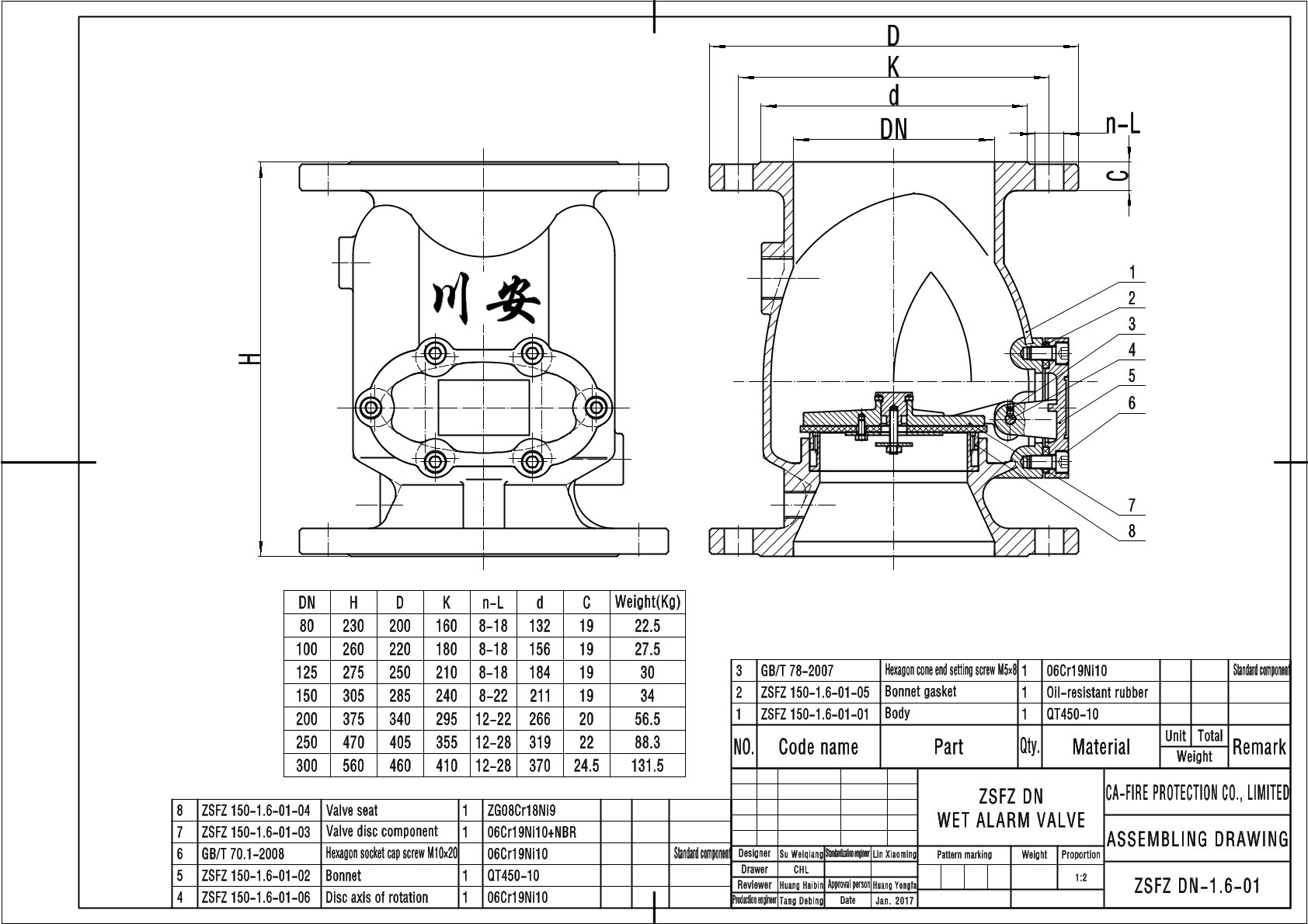
Component 1 — The Alarm Check Valve Body
The alarm check valve body is the primary component — a one-directional clapper valve installed on the main sprinkler riser between the fire water supply and the distribution pipework. In standby, water pressure on both sides of the clapper keeps it seated, preventing backflow while holding the distribution network fully pressurised.
When one or more sprinkler heads open thermally during a fire, downstream pressure drops. The resulting pressure differential lifts the clapper off its seat, allowing water to flow through the valve into the distribution network. Simultaneously, water enters the alarm port — a tapped connection in the valve body that routes flow to the retard chamber and alarm devices.
CA-FIRE’s alarm check valve bodies are available in six configurations:
- ZSFZ Flanged Wet Alarm Valve — DN65–DN300, cast iron, standard indoor wet-pipe
- ZSFC Dry Alarm Valve — DN100–DN200, with pneumatic accelerator, freeze-risk environments
- ZSFZ-Ex Stainless Steel — DN50–DN350, SS304/SS316, coastal/offshore/Ex environments
- ZSFZ-G Grooved — DN100–DN250, Victaulic-compatible IPS groove
- ZSFY Pre-Action — DN80–DN250, single & double interlock, data centres / museums
- ZSFW Threaded — DN32–DN50, G/BSP or NPT thread, residential & small zone
Component 2 — OS&Y Isolation Gate Valve
The OS&Y gate valve (Outside Screw and Yoke) is installed immediately upstream of the alarm check valve body on the supply main. Its purpose is to isolate the sprinkler system from the water supply during maintenance, testing, and after-fire reset operations.
The rising stem position provides visual confirmation of valve status at a glance: an extended stem means the valve is open; a retracted stem means it is closed — no need to open a panel or check a dial indicator to confirm the isolation valve position.
The OS&Y isolation valve upstream of the alarm check valve must be equipped with a tamper switch — a supervisory electrical device connected to the fire alarm control panel that generates an alarm signal if the valve is moved from its fully-open position. Valves without tamper switches do not meet NFPA 13 Section 6.1 or GB 50084 Chapter 8 supervisory requirements.
Component 3 — Retard Chamber
The retard chamber is one of the most misunderstood components in the alarm check valve assembly — and one of the most important. Its function is to prevent false alarms from water hammer, pump start surges, and brief pressure fluctuations that momentarily lift the clapper without representing a genuine fire event.
The retard chamber is a small sealed pressure vessel with a calibrated drain orifice at the bottom, installed between the alarm port and the water motor alarm gong and pressure switch. Here is what happens in two scenarios:
NFPA 13 Section 8.2.6 mandates a retard chamber for any alarm valve connected to a variable-pressure water supply — which includes virtually all municipal mains and most building pressure-boosted systems. A retard chamber is only optional when the supply is a dedicated fire pump with constant, fully regulated, surge-free pressure. In practice, always specify a retard chamber.
Component 4 — Water Motor Alarm Gong
The water motor alarm gong (also called the hydraulic alarm gong or water-driven bell) is the mandatory audible alarm device for every wet-pipe sprinkler system under both GB 5135.6 and NFPA 13. Its defining characteristic is that it requires no electrical power to operate — it is driven entirely by water flow from the alarm port.
When water flows from the retard chamber to the gong, it drives a small turbine inside the gong housing, which strikes the bell repeatedly at approximately 75–90 dB at 3 metres — loud enough to be heard outside the building from the valve room location, as required by code. GB 50084 specifies the mounting height and drainage requirements for alarm gong installation in valve rooms.
The water motor alarm gong provides a fire alarm output that is independent of the building’s electrical system, fire alarm control panel, and battery backup power. In a fire event that has disrupted electrical supplies — a common scenario in severe fires — the water motor gong continues to sound as long as water is flowing.
Component 5 — Alarm Pressure Switch
The alarm pressure switch is the electrical counterpart to the water motor alarm gong. Installed on the alarm trim pipework, it monitors water pressure in the alarm circuit. When sustained water flow fills the retard chamber and pressure builds, the switch closes its electrical contacts, sending a 24VDC signal to the fire alarm control panel (FACP). This signal simultaneously:
- Activates the zone alarm on the FACP — identifying which alarm valve station has operated
- Triggers the automatic fire pump start sequence (via the pump controller)
- Sends a signal to the building management system (BMS) for remote monitoring
- Initiates automatic notification to the fire brigade monitoring centre where connected
Components 6 & 7 — Supply and System Pressure Gauges
Two pressure gauges are installed on every alarm valve station — one on the supply (upstream) side and one on the system (downstream) side. Together they provide continuous passive monitoring of the alarm valve’s standby condition without any active testing procedure.
The most important diagnostic reading is the differential between supply and system pressure. In a correctly functioning standby system, both gauges should read the same pressure — confirming the clapper is fully seated with zero leakage. Any differential indicates the clapper is not sealing properly and requires inspection.
Component 8 — Main Drain Valve
The main drain valve is installed on the system side (downstream) of the alarm check valve body. NFPA 13 and GB 50084 both require the main drain valve to be the same nominal DN size as the alarm valve body — a DN100 alarm valve requires a DN100 main drain valve. Undersizing the drain valve would limit the drain flow rate and extend system drain-down time unacceptably after activation.
The main drain valve serves two purposes:
- Post-activation draining: After a fire event, the entire downstream sprinkler system must be drained before replacement sprinkler heads can be installed and the system refilled.
- Annual trip test (NFPA 25): Opening the main drain valve fully — with the alarm valve open — verifies adequate water supply pressure and flow rate. The residual pressure is recorded and compared year-on-year to detect any deterioration in supply capacity.
Component 9 — Inspector’s Test Valve
The inspector’s test valve is a small-bore valve located at the hydraulically most remote point of the sprinkler distribution system — the point furthest from the alarm valve station in terms of pipe resistance. It is sized to simulate the flow rate of a single open sprinkler head at minimum design pressure.
The quarterly alarm trip test (required by NFPA 25 and GB 50116) is performed by opening the inspector’s test valve and verifying that:
- The water motor alarm gong activates within 90 seconds (NFPA 13 / NFPA 25 requirement)
- The alarm pressure switch sends a signal to the fire alarm panel
- The fire pump starts automatically (where applicable)
How All 9 Components Work Together — Activation Sequence
Understanding how the components interact during an actual fire activation shows why the alarm check valve assembly is a genuinely integrated system:
Assembly Differences by System Type
While all alarm check valve assemblies share the 9 core components described above, there are important differences between wet-pipe, dry-pipe, and pre-action assemblies that affect the trim configuration:
How to Specify a Complete Alarm Valve Assembly
When ordering a complete alarm check valve assembly from CA-FIRE, the following information is required to ensure the correct station components are supplied:
Alarm Check Valve Assembly — Maintenance Schedule
NFPA 25 and GB 50116 define a clear maintenance schedule for alarm valve assemblies. The table below summarises the key tasks by frequency:
CA-FIRE supplies replacement clapper assemblies and EPDM seat seals by model number and DN size for all ZSFZ, ZSFC, ZSFZ-G, and ZSFW alarm valve bodies. Contact sales@ca-fire.com with the model designation and DN size for a replacement parts quotation.
Alarm Valve Assembly
Fire Sprinkler System
Water Motor Alarm Gong
Retard Chamber
NFPA 13
GB 5135.6
→Wet Alarm Valve ZSFZ — DN65–DN300
→Dry Alarm Valve ZSFC — DN100–DN200
→Stainless Steel Alarm Valve — DN50–DN350
→Grooved Alarm Valve ZSFZ-G
→Pre-Action Alarm Valve ZSFY
→Fire Sprinkler Alarm Valve ZSFW
→All Alarm Check Valves →