|
Selection Guide
March 2026 · 9 min read
Gate Valve Types: How to Choose the Right One for Your System
Gate valves come in several distinct types — and the differences matter. Specifying the wrong type means either a valve that doesn't fit the piping system, fails NFPA 13 compliance, or requires replacement within a year. This guide cuts through the classification system so you can match the right gate valve type to your application first time.
How Gate Valves Are Classified
A gate valve specification is defined by three independent choices. Each choice is made separately, and each matters for a different reason:
|
Dimension 1 — Stem Type
Rising stem (OS&Y) or non-rising stem (NRS). This determines how open/closed position is indicated and how much headroom the valve needs above the handwheel. The most important choice for fire protection compliance.
|
|
|
Dimension 2 — End Connection
Flanged (bolted, ANSI or DIN) or grooved (Victaulic-compatible coupling). This must match the piping system already on site. Flanged valves are available in larger sizes; grooved valves install faster.
|
|
|
Dimension 3 — Supervisory Capability
Standard (no switch), tamper switch (NFPA 72 alarm on partial close), or dual signal (confirms open AND closed separately). Required where NFPA 72 supervisory monitoring applies — essentially all supervised fire protection systems.
|
Note on gate disc (wedge) type: Resilient wedge, solid wedge and flexible wedge are all sub-types of the gate disc itself — this affects sealing performance and application suitability but does not change the stem type, end connection or supervisory classification. Wedge type is covered separately in Section 4 below.
Dimension 1 — Stem Type: Rising vs Non-Rising
Stem type is the most consequential choice for fire protection systems because it determines how the valve's open/closed position is indicated — which NFPA 13 requires to be unambiguous and visible from a distance.
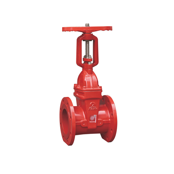
Rising Stem — OS&Y
The threaded stem passes through a yoke nut outside the valve body and rises upward as the valve opens. When the stem is fully extended above the handwheel, the valve is open. When retracted, it is closed. No interpretation needed — visible from 10+ metres away.
Choose when:
✓ Position must be visible at a distance (pump rooms, riser rooms)
✓ NFPA 13 standard for above-ground supply mains
✓ Headroom is available above the handwheel
✓ Fire pump rooms and valve houses
Available: Flanged DN50–DN400 · Grooved DN50–DN300
|
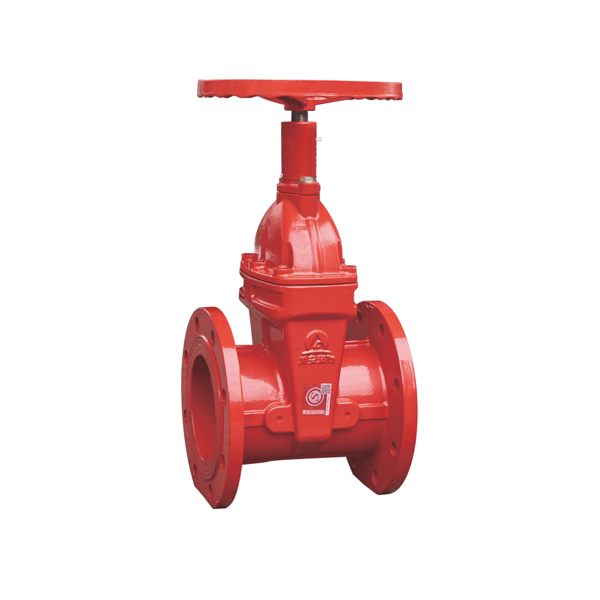
Non-Rising Stem — NRS
The stem threads are inside the valve body — the stem rotates in place without rising. A dial position indicator on the handwheel hub shows the open/closed position as the handwheel is turned. No headroom required above the handwheel.
Choose when:
✓ Underground or pit-mounted installation
✓ Ceiling-level or tight-headroom installation
✓ Buried water mains (with extension spindle)
✓ Where compact height is required
Available: Flanged DN50–DN400
|
| Factor |
OS&Y Rising Stem |
NRS Non-Rising Stem |
| Position indication |
Stem extends visibly — seen from distance |
Dial indicator on handwheel hub |
| Headroom needed |
Yes — stem rises above handwheel when open |
No — stem stays at constant height |
| Underground use |
Not suitable without extension |
✅ Standard for buried pipelines |
| NFPA 13 compliance |
✅ Explicitly listed |
✅ Explicitly listed |
| Stem packing |
External — easy to inspect and replace |
Internal — less accessible |
Dimension 2 — End Connection: Flanged vs Grooved
End connection must match the piping system already in place. Mixing flanged and grooved requires adaptors — which add cost and potential leak points. Confirm the piping system type before ordering.
🔩 Flanged End Connection
Bolted flanges on both ends — ANSI B16.1 Class 125 (North America, Middle East, SE Asia) or DIN 2501 PN16 (Europe, international). Requires flange gaskets and bolts. Slower to install but the standard for fire pump rooms, large-bore mains and any DN300+ application.
Size range: DN50–DN400 · Both ANSI and DIN available
|
⚡ Grooved End Connection
Circumferential grooves machined to ANSI/AWWA C606 standard — compatible with Victaulic and all major grooved coupling brands. Coupling clamps over the groove; no flange gaskets or bolts. Significantly faster to install. Standard in high-rise building fire protection systems.
Size range: DN50–DN300 · AWWA C606 compliant
|
| Factor |
Flanged |
Grooved |
| Installation time |
Slower — flange bolting and gasket required |
✅ Fast — coupling clamps on without tools |
| Max size available |
✅ DN50–DN400 (up to 16") |
DN50–DN300 (up to 12") |
| Standard |
ANSI B16.1 Class 125 or DIN 2501 PN16 |
ANSI/AWWA C606 — Victaulic compatible |
| Common in |
Pump rooms, large-bore mains, industrial |
High-rise buildings, grooved fire systems |
| Fire pump suction |
✅ Standard — flanged connections on pump |
Possible with adaptors; flanged preferred |
Dimension 3 — Supervisory Capability
NFPA 72 requires that control valves on supervised fire protection systems be monitored by supervisory switches wired to the fire alarm control panel (FACP). The switch activates a supervisory alarm if the valve is moved from its fully-open position. Three levels of supervisory capability are available:
Standard
No electrical switch. Position shown by rising stem (OS&Y) or dial (NRS) only. Manual inspection required.
Use for: non-supervised systems, general industrial isolation
|
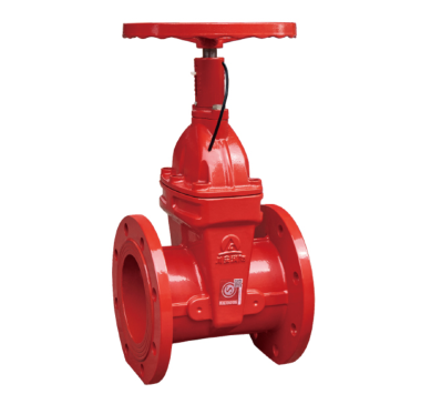
Tamper Switch
Integral SPDT switch activates within 2 turns of handwheel if valve leaves fully-open position. Sends tamper alarm to FACP. NFPA 72 compliant. 24VDC / 120VAC, IP54.
Use for: NFPA 72 supervised fire systems — standard requirement
|
Dual Signal
Two independent micro-switches: SW1 confirms valve is fully open, SW2 confirms valve is fully closed. Both signals available simultaneously. Integrates with BMS for remote status display.
Use for: BMS integration, remote monitoring, high-security systems
|
When is a tamper switch mandatory? NFPA 72 requires supervisory monitoring of all control valves in a supervised fire sprinkler system — which includes virtually all commercial, industrial and multi-residential buildings with a fire alarm system. If there is a FACP on the project, the gate valves on sprinkler supply mains almost certainly require tamper switches. Confirm with the fire alarm designer.
Gate Disc (Wedge) Type: Resilient, Solid or Flexible?
The gate disc type determines how the valve seals when closed and how it performs over long periods between operations. For fire protection and water supply applications, resilient wedge is the correct choice in almost every case.
| Wedge Type |
How It Seals |
Advantages |
Best Application |
| Resilient Wedge |
EPDM rubber encapsulation deforms against both seat faces — rubber-to-metal seal |
Zero-leak shutoff · No seat corrosion · Low operating torque · Seals reliably after years idle |
✅ Fire protection, water distribution — recommended for all new installations |
| Solid Wedge |
Single rigid metal wedge presses against both seats — metal-to-metal seal |
Simple, strong · Handles high temperature · No rubber to degrade |
Steam, high-pressure, high-temperature process pipework |
| Flexible Wedge |
Single wedge with a circumferential groove allowing slight flexing to compensate for seat misalignment |
Compensates for thermal distortion · Good seal even if seats not perfectly parallel |
Steam and thermal cycling — power station and boiler pipework |
Fire protection note: Do not specify solid wedge gate valves for fire sprinkler supply mains. Solid wedge valves that sit idle for months or years can develop corrosion between the metal gate and metal seat faces — making the valve difficult or impossible to close fully when needed. Resilient wedge gate valves with EPDM encapsulation eliminate this risk.
Complete Selection Matrix — Match Application to Gate Valve Type
Use this matrix to identify the right combination of stem type, end connection and supervisory capability for your specific installation:
| Application |
Stem |
End Connection |
Supervisory |
CA-FIRE Product |
| Sprinkler supply main — pump room (above ground) |
Rising (OS&Y) |
Flanged |
Tamper switch |
OS&Y Gate Valve → |
| Underground supply valve / buried main |
Non-rising (NRS) |
Flanged |
Standard or tamper |
NRS Gate Valve → |
| High-rise zone control valve (grooved pipework) |
Non-rising (NRS) |
Grooved |
Tamper switch |
Tamper Switch Valve → |
| BMS-integrated valve status monitoring |
Non-rising (NRS) |
Grooved |
Dual signal |
Signal Gate Valve → |
| Grooved pipework isolation (no supervision) |
Non-rising (NRS) |
Grooved |
Standard |
Grooved Gate Valve → |
| Grooved pipework — OS&Y visibility required |
Rising (OS&Y) |
Grooved |
Standard |
Rising Stem Grooved → |
| Fire pump suction / discharge (large bore) |
Rising (OS&Y) |
Flanged DN150–DN300 |
Standard or tamper |
OS&Y Gate Valve → |
Frequently Asked Questions
Q1 — What are the main types of gate valve?
Gate valves are classified by three dimensions: stem type (rising stem OS&Y or non-rising stem NRS), end connection (flanged or grooved), and supervisory capability (standard, tamper switch, or dual signal). Additionally, the gate disc type (resilient wedge, solid wedge, or flexible wedge) affects sealing performance. The right combination depends on installation headroom, piping system type, and NFPA 72 monitoring requirements.
Q2 — What is the difference between a rising stem and non-rising stem gate valve?
A rising stem (OS&Y) gate valve has a stem that extends upward above the handwheel when open — the position is immediately visible from a distance. It needs headroom above the handwheel. An NRS gate valve has a stem that rotates internally without rising; a dial indicator shows position. NRS is more compact and suited for underground or confined installations. Both are NFPA 13 compliant.
Q3 — What is the difference between flanged and grooved gate valves?
Flanged gate valves connect via bolted flanges (ANSI B16.1 or DIN PN16) — slower to install, available up to DN400, standard for pump rooms and large-bore mains. Grooved gate valves connect via AWWA C606 couplings — faster installation, available up to DN300, widely used in high-rise fire protection systems. The choice must match the piping system on site.
Q4 — What is a resilient wedge gate valve and when should I use it?
A resilient wedge gate valve has a gate disc fully encapsulated in EPDM rubber. The rubber deforms to seal against the seat faces — zero-leak shutoff, no metal-to-metal corrosion, reliable after years idle. Use it for fire protection and water distribution — it is the correct disc type for almost all new fire sprinkler gate valve installations. See the CA-FIRE resilient wedge gate valve.
Q5 — When do I need a gate valve with a tamper switch?
Whenever the sprinkler system has a fire alarm control panel (FACP) and the valve is on a sprinkler supply main. NFPA 72 requires supervisory monitoring of control valves in supervised fire protection systems. The tamper switch sends an alarm signal to the FACP within 2 turns if the valve leaves its fully-open position. See the CA-FIRE gate valve with tamper switch.
Related Articles
|
What Is a Gate Valve?
How a gate valve works, its main parts, and where it's used in fire protection systems.
Read article →
|
Gate Valve vs Ball Valve
Key differences, pressure drop, and why fire protection always requires gate valves.
Read article →
|
|