Home ›Blog ›Gate Valve vs Globe Valve
|
Technical Guide Gate Valve vs Globe Valve: Key Differences ExplainedGate valves and globe valves are both used in pipelines, but they serve fundamentally different purposes. A gate valve isolates — it is either fully open or fully closed, with almost no pressure drop. A globe valve controls — it can throttle and regulate flow, but always at the cost of higher pressure drop. Understanding this one distinction is the key to specifying correctly. What Are Gate Valves and Globe Valves?A gate valve uses a flat or wedge-shaped gate disc that rises or lowers perpendicular to the flow path. When fully raised, the bore is completely unobstructed — the valve is full-bore and the pipe diameter is maintained. When lowered, the gate presses against two valve seats to seal the flow completely. Gate valves are designed for isolation only: fully open or fully closed. A globe valve uses a plug-type disc that moves up and down against a curved (spherical) seat inside the valve body. The flow path inside a globe valve makes an S-shape, travelling up through the seat and back down. This creates a more tortuous path — and a higher pressure drop — but allows precise modulation of flow rate by raising the disc partially off the seat. Globe valves are designed for flow control: fully open, throttled, or fully closed. Gate Valve vs Globe Valve: Head-to-Head
Pressure Drop: The Critical DifferenceThe pressure drop difference between a gate valve and a globe valve is the most important factor for pipeline engineers. When fully open, a full-bore gate valve creates essentially zero restriction — the flow path is a straight bore equal to the pipe diameter. There are no direction changes, no narrowing, no obstruction. A globe valve, even when fully open, forces water to travel upward through the seat, over the disc, and back downward before exiting. This S-shaped path creates a pressure drop 3 to 10 times higher than an equivalent gate valve at the same flow rate. This is significant in hydraulic calculations for fire sprinkler systems, water distribution networks, and any piping system where maintaining design pressure at the most remote outlet is critical.
Engineering note: When modelling fire sprinkler systems to NFPA 13, globe valves must be included in the hydraulic calculation as a significant friction loss component. Gate valves on supply mains can typically be treated as negligible. This is one reason why gate valves — not globe valves — are the standard choice for sprinkler system isolation.
Flow Control: Globe Valve Wins — But at a CostThe globe valve's S-shaped internal flow path — which creates its high pressure drop — is also the reason it excels at flow regulation. As the plug disc is raised partially off the seat, flow increases proportionally and predictably. The relationship between disc position and flow rate is consistent and controllable, making globe valves the standard choice for throttling applications. A gate valve should never be used for throttling. At partial open positions, the gate disc vibrates in the flow stream, rapidly eroding the disc and seat faces. A gate valve used as a flow regulator will develop leakage within months and fail to seal completely when closed. Gate valves are designed to be either fully open (gate completely out of the flow) or fully closed (gate fully seated). Common mistake: Using a gate valve to reduce flow by leaving it partially open. This causes seat and disc erosion leading to permanent leakage. If flow regulation is needed, always install a globe valve or control valve — not a gate valve.
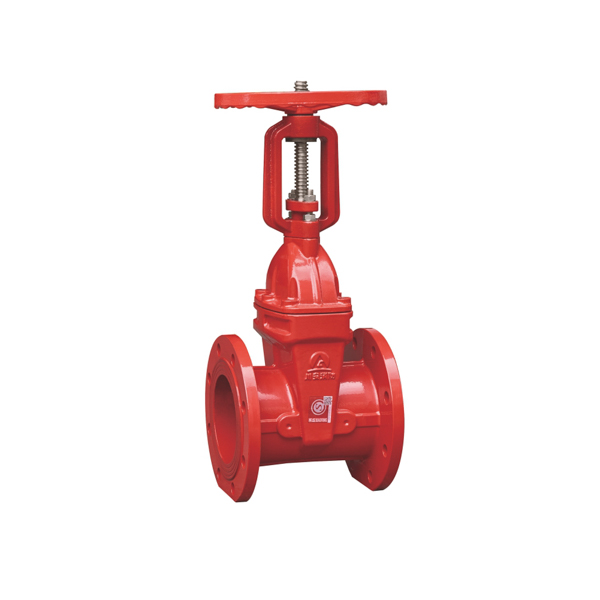
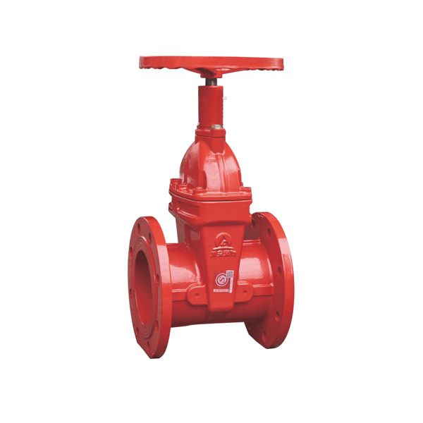
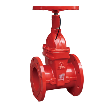
Fire Protection: Why Gate Valves Are RequiredIn fire protection systems, gate valves are mandated by NFPA 13 for isolation of sprinkler supply mains. Globe valves are not accepted as substitutes for three specific reasons: 1. Full-bore flow requirementNFPA 13 hydraulic calculations assume that isolation valves on supply mains contribute negligible pressure drop. A gate valve, being full-bore, satisfies this. A globe valve's high pressure drop would reduce water delivery to sprinkler heads during a fire event — potentially below the design density required to control the fire. 2. Visual position indicationNFPA 13 requires that control valves on fire protection systems provide a clear visual indication of open or closed status. The rising stem of an OS&Y gate valve is clearly extended (open) or retracted (closed) from a distance. The NRS gate valve provides this through a dial indicator. Globe valves do not provide the same unambiguous distance-visible position indication. 3. Tamper switch compatibilityNFPA 72 requires supervisory monitoring of sprinkler control valves via tamper switches connected to the fire alarm panel. Gate valves with integral supervisory switches are standard products — available in OS&Y and grooved configurations. Globe valves are not designed with tamper switch provisions for fire protection applications. 🔥 CA-FIRE Fire Protection Gate Valves
CA-FIRE manufactures the full range of NFPA 13 compliant gate valves: OS&Y rising stem gate valves, NRS gate valves with dial indicator, gate valves with tamper switch, and dual-signal gate valves for BMS integration. DN50–DN400, PN16, full-bore, resilient-seated. Available with ANSI B16.1 flanged, DIN PN16 flanged, or AWWA C606 grooved end connections. When to Use a Gate Valve vs a Globe Valve
Can a Globe Valve Replace a Gate Valve?In general pipework, a globe valve can technically replace a gate valve for on/off isolation — but the higher pressure drop means the system hydraulics must be recalculated to confirm adequate flow at all outlets. In most cases this results in larger pipe sizes or higher pump pressure to compensate, making the substitution costly. In fire protection systems, a globe valve cannot replace a gate valve on supply mains. NFPA 13 is specific about acceptable valve types. A globe valve does not satisfy the full-bore, visual indication, and tamper switch requirements. Any deviation from the listed valve types requires approval from the authority having jurisdiction (AHJ) and would likely be refused. Key rule: Gate valves isolate, globe valves regulate. If you need to control flow rate — use a globe valve. If you need to isolate a pipe with minimal headloss — use a gate valve. Mixing up the two creates either a system with unacceptable pressure drop (globe used for isolation) or permanent seat damage (gate used for throttling).
Frequently Asked QuestionsRelated Articles
|
⚡ The One Rule
Gate valve = isolation. Globe valve = flow control. Need a Gate Valve Quote?
CA-FIRE manufactures fire protection gate valves DN50–DN400. Factory direct from Fujian, China. WhatsApp: +86 181-5036-2095 |