Model ZSDF8 / ZSXDF8 — Victaulic-Compatible Grooved Coupling · Fire Isolation Valve
Grooved Butterfly Valve
Victaulic-compatible grooved coupling butterfly valve for fire sprinkler, standpipe, and foam suppression systems on grooved steel pipe. Meets AWWA C606 and ISO 6182-12 groove dimensions. Four variants — gear and lever, with or without DC24V tamper switch. DN50–DN300 (gear) / DN50–DN150 (lever), 1.6 MPa. Up to 40% faster installation than flanged wafer valves. GB 5135 / NFPA 13 certified.
Four Model Variants
ZSDF8 Family — Select by Actuator & Supervision
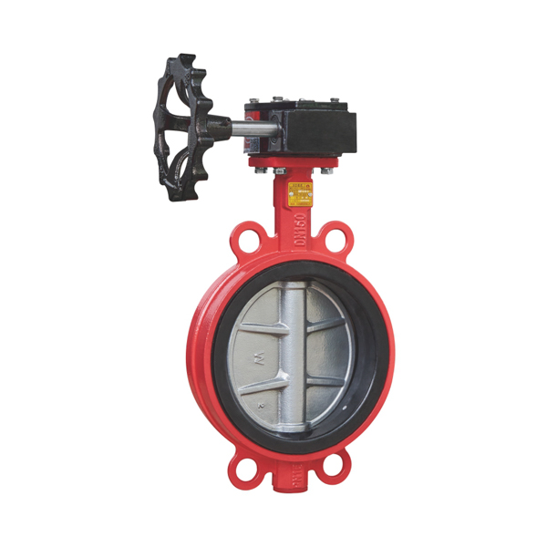
All four models share the same grooved body, EPDM seat, and 1.6 MPa pressure rating. Select based on two criteria: actuator type (gear vs. lever) and supervision requirement (tamper switch vs. none).
- DN50–DN300, worm gear handwheel
- DC24V 0.5A tamper switch — NFPA 72 Ch.17
- Main riser, zone control, pump isolation
- Required for supervised fire mains with FACP
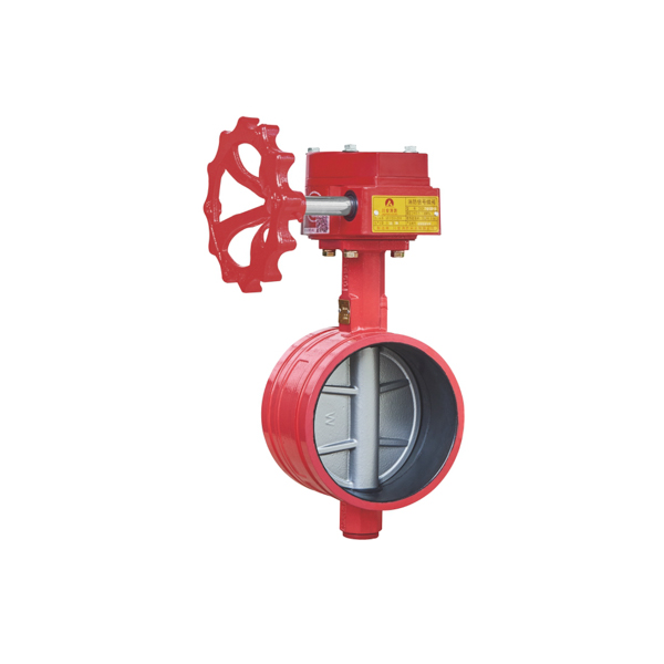
- DN50–DN300, worm gear handwheel
- No tamper switch — lower cost
- Drain valves, test lines, pump test loops
- Physical lock-open supervision only
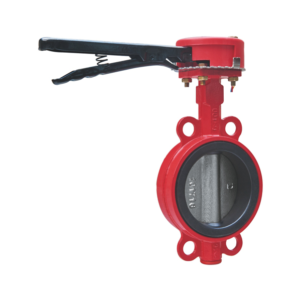
- DN50–DN150, quarter-turn lever
- DC24V 0.5A tamper switch
- Zone control valves, branch isolations
- Fast operation + FACP supervisory monitoring
- DN50–DN150, quarter-turn lever
- No tamper switch
- Inspector test, drain, test-and-drain
- Non-supervised grooved branch valves
Key Features
Why Specify the ZSDF8 Series
Eight design points that make the ZSDF8 / ZSXDF8 the standard grooved butterfly valve for fire protection on commercial, high-rise, offshore, and industrial projects.
Technical Data
Full Technical Specifications — All Four Models
All four ZSDF8 variants share the same grooved body, EPDM seat, 1.6 MPa rating, and GB 5135 certification. Select by actuator type and supervision method.
| Parameter | ZSXDF8 Gear+Signal | ZSDF8 Gear | ZSXDF8-S Lever+Signal | ZSDF8-S Lever |
|---|---|---|---|---|
| Model Number | ZSXDF8-Q-50-300-16 | ZSDF8-Q-50-300-16 | ZSXDF8-S-Q-50-150-16 | ZSDF8-S-Q-50-150-16 |
| Nominal Diameter | DN50–DN300 | DN50–DN300 | DN50–DN150 | DN50–DN150 |
| Working Pressure | 1.6 MPa (16 bar / 232 psi) | |||
| Strength Test | 6.4 MPa | |||
| Seal Test | 3.2 MPa | |||
| Media | Water · AFFF foam-water · AR-AFFF · Protein foam | |||
| Actuator | Worm gear | Worm gear | Lever handle | Lever handle |
| Tamper Switch | DC24V 0.5A | None | DC24V 0.5A | None |
| Connection | Grooved ends — Victaulic / AWWA C606 / ISO 6182-12 | |||
| Body Material | Ductile cast iron GGG40 / Stainless steel SS316 | |||
| Seat Material | EPDM (bi-directional) | |||
| Media Temperature | 0–80°C | 4–70°C | 0–80°C | 4–70°C |
| GB Standard | GB 5135.13 | GB 5135.2 | GB 5135.13 | GB 5135.2 |
Structural Dimensions
Face-to-Face Length — Grooved End
Grooved butterfly valve face-to-face dimensions for pipe spool layout and interference checks. Grooved F/F is 15–85 mm longer than equivalent wafer type because grooved pipe ends must protrude beyond the valve body for coupling engagement. All dimensions in mm.
| DN (mm) | 50 | 65 | 80 | 100 | 125 | 150 | 200 | 250 | 300 |
|---|---|---|---|---|---|---|---|---|---|
| F/F (mm) | 80 | 80 | 80 | 95 | 102 | 110 | 120 | 160 | 165 |
Installation Guide
How to Install the ZSDF8 Grooved Butterfly Valve
Six-step installation and commissioning sequence using standard grooved mechanical pipe couplings.
Applications
Where the Grooved Butterfly Valve Is Specified
Standard valve on any fire suppression project using grooved steel pipe throughout. Key application categories:
Grooved vs. Wafer
Grooved (This Page) vs. Wafer (ZSDF7)
CA-FIRE offers identical disc, seat, and performance specifications in both connection types. The connection method is determined by your pipe system design.
| Factor | Grooved ZSDF8 — This Page | Wafer ZSDF7 |
|---|---|---|
| Connection | Grooved coupling (Victaulic) | Between flanges (ANSI/DIN/GB) |
| Installation | No flange — grooved coupling only | Requires flanged pipe ends |
| Assembly Speed | Faster — no bolt torquing | Full bolt circle required |
| Pipe Movement | 1–3° angular deflection (flexible coupling) | Rigid connection |
| Face-to-Face (DN50–DN300) | 80–165 mm | 45–80 mm |
| Valve Removal | Uncouple only — no pipe cutting | Remove flange bolts |
| Best for | Grooved pipe systems, offshore, modular skids | Flanged systems, tight F/F spaces |
| Actuator Options | Gear or Lever (DN50–DN300 / DN50–DN150) | Gear (ZSDF7) or Lever (ZSDF7-S) |
Mixing grooved and flanged connection types on the same fire main is not recommended. Specify one connection type throughout each system zone.
FAQ
Frequently Asked Questions
Common questions about the ZSDF8 / ZSXDF8 grooved butterfly valve for fire protection.
Butterfly Valve Family
Other Butterfly Valves in the CA-FIRE Range
All share the same 1.6 MPa rating, EPDM seat, and GB 5135 certification.