Vertical Foam Bladder Tank — PHY Series
Compact Floor Footprint · 0.5–13.0 m³ · 8–120 L/s · DN80–DN250 · ±0.3% Mixing Accuracy · No Electricity · NFPA 11 / GB · Above-Ground Plant Rooms
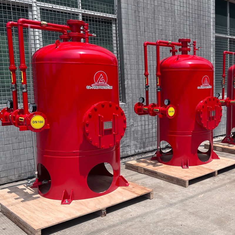
Vertical Foam Bladder Tank
Upright pressure vessel storing foam concentrate in an internal rubber bladder — minimising floor footprint while utilising available ceiling height. The preferred vertical bladder tank for petrochemical plant rooms, refinery fire pump buildings, airport suppression equipment rooms and above-ground industrial installations where floor space is constrained. Compatible with NFPA 11, NFPA 16 and GB 50151.
Vertical Foam Bladder Tank — Technical Specifications
| Product Type | Vertical Foam Bladder Tank — PHY Series Pressure Proportioning Device |
| Working Pressure Range | 0.6 – 1.2 MPa |
| Pressure Drop | ≤ 0.2 MPa |
| Strength Test Pressure | 1.5 MPa |
| Seal Test Pressure | 1.32 MPa |
| Tank Volume | 0.5 m³ – 13.0 m³ (customisable to project) |
| Main Pipe Diameter | DN80 – DN250 (customisable to project) |
| Proportioner Flow Range | 8 L/s – 120 L/s (model-dependent; customisable) |
| Foam Concentrate Mixing Ratio | 3% or 6% |
| Mixing Accuracy | ± 0.3% of rated ratio — across full flow range |
| Operating Temperature | 4 – 70 °C |
| Tank Body Material | Carbon steel, internal and external anti-corrosion epoxy coating |
| Bladder Material | Chemical-resistant EPDM / NBR rubber — compatible with AFFF, FFFP, AR-AFFF, protein foam |
| Electricity Required | None — fully hydraulic proportioning |
| Certifications | GB standard · ISO 9001 · CE |
| Applicable Standards | NFPA 11 · NFPA 16 · GB 50151 |
How the Vertical Foam Bladder Tank Works
The PHY series operates on a fully hydraulic displacement proportioning principle — no electricity, no diesel engine, no pneumatic supply required at any stage of operation.
PHY Series — Model Parameters
Select the PHY model that matches your system design flow rate. Tank volume and pipe diameter are customisable — CA-FIRE provides project-specific hydraulic sizing at no charge.
| Model | Flow Rate (L/s) 3% Ratio |
Flow Rate (L/s) 6% Ratio |
Foam Output (L/s) 3% Ratio |
Foam Output (L/s) 6% Ratio |
Working Pressure (MPa) | Typical Volume (m³) | Main Pipe DN |
|---|---|---|---|---|---|---|---|
| PHY 4 | 4 | 4 | 0.12 | 0.24 | 0.6–1.2 | 0.5–2.0 | DN80–DN100 |
| PHY 8 | 8 | 8 | 0.24 | 0.48 | 0.6–1.2 | 0.5–2.0 | DN80–DN100 |
| PHY 16 | 16 | 16 | 0.48 | 0.96 | 0.6–1.2 | 1.0–4.0 | DN100–DN150 |
| PHY 24 | 24 | 24 | 0.72 | 1.44 | 0.6–1.2 | 1.5–6.0 | DN125–DN150 |
| PHY 32 | 32 | 32 | 0.96 | 1.92 | 0.6–1.2 | 2.0–8.0 | DN150–DN200 |
| PHY 48 | 48 | 48 | 1.44 | 2.88 | 0.6–1.2 | 3.0–10.0 | DN200–DN250 |
| PHY 64 | 64 | 64 | 1.92 | 3.48 | 0.6–1.2 | 4.0–13.0 | DN200–DN250 |
| PHY 76 | 76 | 76 | 2.28 | 4.56 | 0.6–1.2 | 5.0–13.0 | DN200–DN250 |
| PHY 100 | 100 | 100 | 3.00 | 6.00 | 0.6–1.2 | 0.5–13.0 | DN80–DN250 |
| All tank volumes and pipe diameters are customisable to project hydraulic design. Contact CA-FIRE for model selection and free tank volume calculation per NFPA 11 or GB 50151 discharge duration requirements. | |||||||
Typical Applications — Vertical Foam Bladder Tank
Vertical vs. Horizontal Foam Bladder Tank — Selection Guide
Both configurations deliver identical ±0.3% proportioning performance. The choice is driven entirely by your installation space constraints.
| Parameter | Vertical Bladder Tank (PHY) — This Product | Horizontal Bladder Tank (PHYM) |
|---|---|---|
| Floor Footprint | ✓ Compact — minimal floor area | Larger — longer saddle-mounted footprint |
| Installed Height | Higher — requires ceiling clearance | ✓ Low — fits restricted headroom |
| Above-Ground Pump Rooms | ✓ Preferred — maximises floor space | Suitable |
| Underground / Basement | Less suitable | ✓ Preferred — low profile fits |
| Shipboard Installation | Space constraints usually prohibit | ✓ Standard choice for vessels |
| Maximum Flow Rate | 8–120 L/s | 4–360 L/s — widest range |
| Tank Volume Range | 0.5–13.0 m³ | 0.5–13.0 m³ |
| Proportioning Accuracy | ±0.3% | ±0.3% |
| Mixing Ratio | 3% or 6% | 3% or 6% |
| Product Link | This page ↑ | View Horizontal Tank → |
Maintenance Schedule — NFPA 11 Compliance
A structured maintenance programme is required by NFPA 11 Chapter 11 and GB 50281 to ensure the vertical foam bladder tank remains fully operational throughout its service life.
| Frequency | Task |
|---|---|
| Monthly | Visual inspection of tank body, pipework and instrumentation for leaks, corrosion or physical damage. Verify pressure gauge readings on water side and concentrate side — any unexplained differential pressure change warrants investigation for bladder leakage. Confirm all isolation valves are in correct normal positions. |
| Quarterly | Verify concentrate level indicator against original fill record — investigate any unexplained volume reduction. Inspect all flanged joints and valve packing for signs of weeping. Test safety valve and air vent for correct manual operation. |
| Annual | Access the bladder through the top inspection manway — inspect for cuts, stiffening, blistering or chemical attack. Full pressure and seal test to 1.32 MPa. Sample the foam concentrate and test against manufacturer's quality specification. Verify proportioning accuracy at system design flow rate. |
| Every 5–7 Yrs | Preventive bladder replacement regardless of apparent condition. Full internal tank inspection and recoating if required. CA-FIRE supplies replacement bladders for all PHY series models with full installation guidance and technical support. |
Frequently Asked Questions — Vertical Foam Bladder Tank
Send your system flow rate, discharge duration and applicable standard — CA-FIRE returns a sizing recommendation and project price within 24 hours.