Dry Alarm Valve — ZSFC Series with Accelerator
DN100–DN200 · 1.6 MPa · Pneumatic Accelerator · Freeze-Rated to −20°C · GB 5135.2 · NFPA 13
Dry Alarm Valve — ZSFC Series with Accelerator
DN100–DN200 · 1.6 MPa
A dry alarm valve is the control component in a dry-pipe automatic fire sprinkler system — designed for environments where standing water in the distribution pipework would freeze and disable the system. Instead of water, the downstream pipework is charged with compressed air or dry nitrogen at supervisory pressure (0.14–0.28 MPa). Water is held back at the dry alarm valve body. When a sprinkler head opens in a fire, the downstream air pressure drops, the differential clapper trips, and water floods the system to discharge through the open head.
CA-FIRE's ZSFC series dry alarm valve is available in DN100, DN150, and DN200 with flanged connections, rated to 1.6 MPa working pressure, and compliant with GB 5135.2 and NFPA 13. A pneumatic accelerator is matched to all three sizes — reducing water delivery time to under 60 seconds, meeting NFPA 13's mandatory trip time requirement.
The ZSFC is the correct specification for cold storage, unheated warehouses, parking garages, loading dock canopies, and roof spaces. For environments where both freeze protection and false-discharge prevention are required simultaneously, see the pre-action alarm valve. For standard heated buildings, see the wet alarm valve ZSFZ. ← See all alarm check valve types
Dimensional Data — 3 Sizes
| DN Size | Body Height (mm) | Working Pressure | Seal Test | Strength Test | Control Method |
|---|---|---|---|---|---|
| DN100 | 375 | 1.6 MPa | 3.2 MPa | 6.4 MPa | Pneumatic accelerator |
| DN150 | 455 | 1.6 MPa | 3.2 MPa | 6.4 MPa | Pneumatic accelerator |
| DN200 | 610 | 1.6 MPa | 3.2 MPa | 6.4 MPa | Pneumatic accelerator |
How a Dry Alarm Valve Works — Step by Step
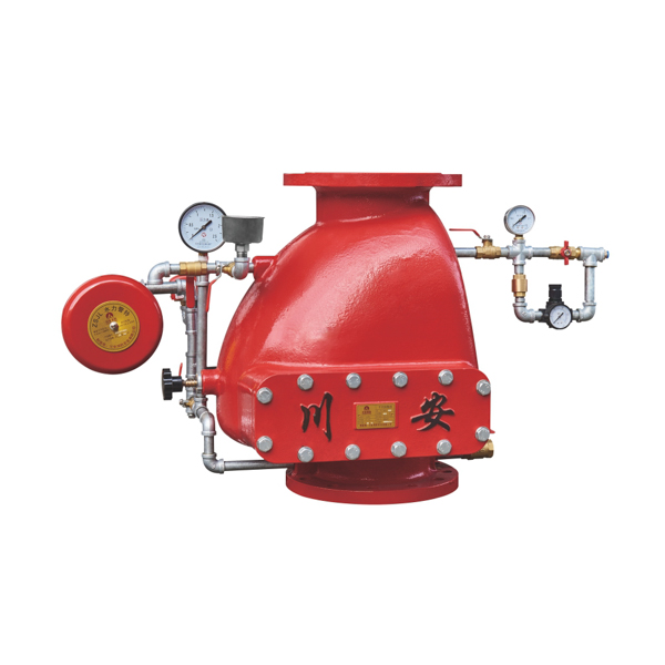
Complete Dry Alarm Valve Station — Components
CA-FIRE supplies the ZSFC dry alarm valve as a valve body only or as a complete matched station assembly. Key difference from a wet alarm valve station: the dry system requires additional air-side components — accelerator, air pressure maintenance device, and low-air alarm switch — that have no equivalent in a wet pipe station.
| # | Component | Side | Function & Notes |
|---|---|---|---|
| 1 | ZSFC Dry Alarm Valve Body | Both | Differential pressure clapper; EPDM rubber facing; DN100/150/200; this product |
| 2 | Pneumatic Accelerator | Air side | Trips clapper on initial pressure drop; achieves <60 s water delivery; required for NFPA 13 compliance on all but the smallest systems |
| 3 | Air Pressure Maintenance Device | Air side | Automatically compensates for minor air leakage; maintains supervisory pressure without manual intervention; prevents spurious low-air alarms |
| 4 | Low-Air Alarm Pressure Switch | Air side | Signals fire alarm panel when supervisory pressure drops below minimum setpoint — early warning of system leak before valve trips; unique to dry pipe systems |
| 5 | System Air Pressure Gauge | Air side | Displays downstream supervisory air pressure; 0–0.5 MPa range; drop from setpoint indicates head activation or system leak |
| 6 | Supply Water Pressure Gauge | Water side | Displays upstream water supply pressure; 0–1.6 MPa range; monitored alongside air gauge in standby |
| 7 | Retard Chamber | Water side | Delays alarm signal 5–30 s; prevents false activations at gong and pressure switch from brief air pressure fluctuations |
| 8 | Water Motor Alarm Gong | Water side | Hydraulically driven mechanical bell; no electrical power; activates when valve trips; mandatory per GB 5135.2 |
| 9 | Alarm Pressure Switch | Water side | Electrical signal to fire alarm panel on valve trip; 24 V DC; zone identification for BMS and remote monitoring |
| 10 | OS&Y Gate Valve (upstream) | Water side | Supply isolation; tamper-switch supervised; locked open in normal operation |
| 11 | Main Drain & Inspector's Test Valve | Water side | Full-flow drain for post-activation reset and annual trip test; inspector's test connection for quarterly partial-flow alarm verification |
Dry vs Wet vs Pre-Action Alarm Valve — Selection Guide
The primary selection driver is whether the distribution pipework will be exposed to freezing temperatures, and whether accidental water discharge is a concern.
| Parameter | Dry Alarm Valve ZSFC (this product) | Wet Alarm Valve ZSFZ | Pre-Action Valve ZSFY |
|---|---|---|---|
| Downstream pipework | Compressed air / dry N₂ | Water (always charged) | Supervisory air |
| Freeze environments | ✓ Yes — to −20°C | ✗ No — pipe will freeze | ✓ Yes |
| Response speed | <60 s with accelerator | ✓ Immediate | Requires detector + head |
| False discharge protection | Low — any single head trips | Low — any single head trips | ✓ High — dual interlock |
| System complexity | Moderate — air system needed | ✓ Simplest | Most complex |
| Maintenance burden | Higher — air system monitoring | ✓ Lowest | Highest |
| Specify when | Freeze risk, no false-discharge concern | Indoor ≥4°C, standard building | Freeze risk + false discharge both critical |
Application Scenarios
Standards & Certifications
| Standard | Scope & Relevance to ZSFC Dry Alarm Valve |
|---|---|
| GB 5135.2-2003 ↗ | 自动喷水灭火系统 第2部分 — Chinese national standard for dry alarm valves governing differential clapper design, seal test (3.2 MPa), strength test (6.4 MPa), trip time requirements, and accelerator performance. ZSFC series holds national fire product type approval certification under this standard. |
| NFPA 13 ↗ | Standard for the Installation of Sprinkler Systems — dry pipe system design requirements, mandatory 60-second water delivery time limit (accelerator required for compliance), supervisory air pressure range (0.14–0.28 MPa / 20–40 psi), and air supply requirements. CA-FIRE provides Cv data per DN size for NFPA 13 hydraulic calculations. |
| NFPA 25 ↗ | Standard for ITM of Water-Based Fire Protection Systems — dry pipe valve inspection schedule, quarterly partial trip test (accelerator trip test), annual full trip test, air maintenance device inspection, and low-air alarm switch function verification. |
| GB 50084 | 自动喷水灭火系统设计规范 — Chinese design code; specifies dry pipe system application conditions, valve room heating requirements (≥4°C), air supply equipment, and dry nitrogen vs compressed air selection guidance for cold-store applications. |
| ISO 9001:2015 ↗ | CA-FIRE QMS certification — covers casting inspection, differential clapper machining tolerances, EPDM material verification, accelerator calibration testing, full-system hydraulic pressure testing, and shipment documentation for all ZSFC sizes. |
Frequently Asked Questions
Typical applications requiring a dry alarm valve: cold storage facilities and blast-freeze warehouses (−18°C to −30°C); unheated loading dock canopies and staging areas; open-deck parking garages in cold climates; building roof spaces and attics without heating; and outdoor canopy areas. For any indoor area consistently maintained above 4°C, the simpler and faster-responding wet alarm valve is the correct choice.
With the pneumatic accelerator installed and calibrated correctly, the dry alarm valve trips within seconds of the initial air pressure drop — before the full air volume has vented. Water delivery time drops below 60 seconds on virtually all practical system sizes. CA-FIRE factory-calibrates and tests the accelerator matched to the ZSFC valve before shipment.
Dry nitrogen from a cylinder supply eliminates both moisture and oxygen from the system side — dramatically reducing internal pipe corrosion and eliminating freeze risk from condensed moisture. For cold-store and blast-freeze applications, dry nitrogen is the preferred medium. The ZSFC valve body is compatible with both media — no modification required.
The low-air alarm setpoint should be set approximately 0.007–0.014 MPa (1–2 psi) below the supervisory pressure setpoint. The accelerator trip point should be set approximately 0.014–0.028 MPa (2–4 psi) below the low-air alarm setpoint. This staggered sequence — supervisory pressure → low-air alarm → accelerator trip → valve trip — ensures the alarm panel receives early warning of a leak, and that the accelerator only trips on a genuine head activation. Do not set the supervisory pressure above 0.28 MPa; higher air pressure increases the trip pressure threshold of the accelerator and can slow response time.
Annually: Full trip test — open the main drain valve and trip the full dry alarm valve to verify water delivery time is within the 60-second NFPA 13 requirement. Inspect retard chamber drain orifice. Verify OS&Y tamper switch function. Recharge system after test and verify accelerator reset correctly.
Every 5 years: Internal inspection — remove differential clapper and inspect seat, hinge, and EPDM facing for wear or deformation. Inspect accelerator internals. Replace EPDM components if compression set or cracking is observed. CA-FIRE supplies replacement clapper assemblies and accelerator service kits — contact [email protected].
For projects with a contractual UL Listing or FM Approval requirement, contact [email protected] to discuss certification options. CA-FIRE provides full project submittal packages: Cv data per DN size, dimensional drawings in DWG/PDF, material certificates, accelerator calibration test records, and GB 5135.2 type approval certificates — all in English. Flange drilling available in ANSI B16.1, DIN 2501, and GB patterns.
Related Products
Valve body only or complete dry alarm valve station assembly · ANSI / DIN / GB flanges · Factory direct · 24 hr quote