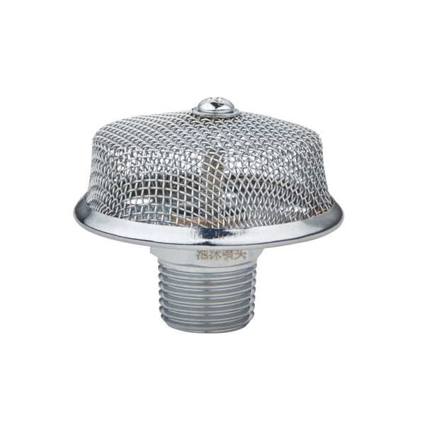
Water-based sprinkler systems cannot suppress flammable liquid fires. Water applied to burning fuel scatters the burning liquid, spreads the fire, and in some cases creates violent steam explosions. For Class B fires — petroleum products, solvents, fuels, oils — the correct suppression agent is foam, and the correct delivery device is a foam sprinkler head. CA-FIRE's PT series open-type air-aspirating foam sprinkler heads are specifically engineered for fixed foam-water sprinkler systems protecting flammable liquid hazards: oil fields, fuel storage facilities, industrial plants, underground car parks, aircraft hangars, and process chemical stores.
The PT series operates on the air-aspirating principle: as the foam solution (pre-mixed foam concentrate and water) passes through the head at pressure, it draws in surrounding air through intake ports, generating expanded foam that is thrown onto the fuel surface as a blanket. This foam blanket achieves suppression through two mechanisms simultaneously — oxygen exclusion (sealing the fuel surface from the atmosphere) and fuel cooling. The foam is self-sealing: it flows across the burning liquid surface, fills any gaps caused by obstructions, and re-heals if disturbed.
Five models — PT0.9 through PT2.0 — provide protection areas from 3×3 m up to 4.4×4.4 m per head at a standard installation height of 3 m, covering the full range of bunded storage areas, process area bays, and underground parking cells typically encountered in petrochemical and industrial facility design.
Also in the CA-FIRE foam protection range: AFFF foam concentrate → · AR-AFFF (alcohol-resistant) foam concentrate → · Deluge Sprinkler System →
How Air-Aspirating Foam Sprinkler Heads Work
- Pre-mix delivery: The foam-water solution (foam concentrate pre-mixed with water at the specified ratio — typically 3% or 6%) is delivered to the head under pressure via the fixed pipe system.
- Venturi acceleration: As the solution passes through the orifice, it accelerates and creates a low-pressure zone around the discharge point — the Venturi effect.
- Air entrainment: Surrounding air is drawn in through dedicated intake ports in the head body. This air mixes with the high-velocity foam solution stream.
- Foam generation: The turbulent mixing of air and foam solution in the expansion chamber generates low-expansion foam (expansion ratio approximately 6–10:1) with stable bubble structure.
- Surface coverage: The expanded foam is thrown onto the protected surface in a controlled spray pattern — the radius and coverage area are determined by the orifice size (PT model number) and installation height.
- Oxygen exclusion: A coherent foam blanket physically seals the fuel surface from atmospheric oxygen. Without oxygen at the fuel surface, combustion cannot be sustained regardless of fuel temperature.
- Self-sealing blanket: Unlike a fixed barrier, foam flows around obstacles on the fuel surface — pipes, structural supports, equipment — re-forming a continuous seal. Water spray cannot achieve this.
- Cooling secondary effect: The water content of the foam provides cooling to reduce re-ignition risk and protect adjacent metal structures.
- Burn-back resistance: Quality AFFF and AR-AFFF foam concentrates (as supplied by CA-FIRE) form a thin aqueous film beneath the foam layer that persists on the fuel surface and resists reignition even after the foam blanket is disturbed.
- No water scatter: Direct water application to burning fuel scatters burning droplets — a foam blanket is applied gently across the surface with no disruptive impact.
PT Series Foam Sprinkler Head Models
PT0.9
Foam · K28.9 · 3×3 mSmallest PT head. Covers a 3×3 m (9 m²) protection area at 3 m installation height. Suited to narrow bunded areas, small tank bund compartments, and tight bay configurations.
| Protection area | 3×3 m (9 m²) |
|---|---|
| Coverage radius | 1.8 m |
| Flow factor K | 28.9 |
| Working pressure | 0.3–0.6 MPa |
| Thread | R:½ |
PT1.1
Foam · K35.3 · 3.2×3.2 mStandard small-bay coverage. Protection area 3.2×3.2 m at 3 m height, 1.8 m coverage radius. Used in standard-width bunded areas and underground parking bays where PT0.9 spacing does not optimise head count.
| Protection area | 3.2×3.2 m (10.2 m²) |
|---|---|
| Coverage radius | 1.8 m |
| Flow factor K | 35.3 |
| Working pressure | 0.3–0.6 MPa |
| Thread | R:½ |
PT1.4
Foam · K42 · 3.6×3.6 m · Most UsedThe most widely specified PT head. 3.6×3.6 m (12.96 m²) coverage at 3 m height, 2.0 m radius. Matches standard bay spacing in Chinese GB 50151 foam-water system designs and NFPA 16 medium-hazard layouts. Standard for underground car parks and process plant bays.
| Protection area | 3.6×3.6 m (12.96 m²) |
|---|---|
| Coverage radius | 2.0 m |
| Flow factor K | 42 |
| Working pressure | 0.3–0.6 MPa |
| Thread | R:½ |
PT1.6
Foam · K48 · 3.6×3.6 mHigher-flow version at the same 3.6×3.6 m coverage area as PT1.4. The larger orifice delivers greater foam solution volume per head, achieving faster fuel surface coverage and higher foam application rate — specified for Extra Hazard flammable liquid risks.
| Protection area | 3.6×3.6 m (12.96 m²) |
|---|---|
| Coverage radius | 2.0 m |
| Flow factor K | 48 |
| Working pressure | 0.3–0.6 MPa |
| Thread | R:½ |
PT2.0
Foam · K60 · 4.4×4.4 m · LargestLargest coverage PT head. 4.4×4.4 m (19.36 m²) protection area at 3 m height, 2.3 m radius. R:¾ thread for increased flow capacity. Suited to large open bunded storage areas, aircraft hangar aprons, and large industrial process bays where minimising head count is a design priority.
| Protection area | 4.4×4.4 m (19.36 m²) |
|---|---|
| Coverage radius | 2.3 m |
| Flow factor K | 60 |
| Working pressure | 0.3–0.6 MPa |
| Thread | R:¾ |
PT Series Complete Technical Parameters
| Model | Connection | Protection Area (m²) | Area Dimensions | Coverage Radius (m) | Flow Factor K | Install Height (m) | Working Pressure (MPa) |
|---|---|---|---|---|---|---|---|
| PT0.9 | R:½ | 9.0 | 3.0 × 3.0 m | 1.8 | 28.9 | 3 | 0.3–0.6 |
| PT1.1 | R:½ | 10.2 | 3.2 × 3.2 m | 1.8 | 35.3 | 3 | 0.3–0.6 |
| PT1.4 ★ | R:½ | 12.96 | 3.6 × 3.6 m | 2.0 | 42 | 3 | 0.3–0.6 |
| PT1.6 | R:½ | 12.96 | 3.6 × 3.6 m | 2.0 | 48 | 3 | 0.3–0.6 |
| PT2.0 ★ | R:¾ | 19.36 | 4.4 × 4.4 m | 2.3 | 60 | 3 | 0.3–0.6 |
★ Most commonly specified. All models open type (no thermal sensing element) — must be installed in a deluge or foam-water sprinkler system. Installation height: 3 m (heads mounted at 3 m above the protected surface). GB 5135 CCCF certified.
Fire Class Coverage — Class A and Class B
Class B — Primary Application ✓
- Flammable liquids (hydrocarbons): petrol, diesel, jet fuel, fuel oil, naphtha, crude oil
- Solvents: xylene, toluene, acetone, MEK, ethyl acetate
- Lubricating and hydraulic oils
- Transformer and turbine oils in switchgear rooms
- Cooking oils in large commercial kitchen extracts
- Use AFFF (3% or 6%) or AR-AFFF for alcohol-based fuels
Class A — Secondary Use ⚠
- Foam from PT heads also wets and suppresses ordinary combustibles (wood, paper, fabric) at the margins of a Class B fire scenario
- Class A foam additive can be used in PT heads to enhance suppression of surrounding combustible materials
- PT heads are not the primary design choice for pure Class A hazards — use standard closed-head sprinklers for Class A only occupancies
- Class C (live electrical): foam is conductive — systems must be electrically isolated before activation in live electrical areas
Compatible CA-FIRE Foam Concentrates
PT series foam sprinkler heads are compatible with all standard low-expansion foam concentrates. CA-FIRE supplies a full range of foam concentrates matched to the PT head range. Correct concentrate selection is determined by the fuel type — hydrocarbon fuels use AFFF, while polar solvents and alcohol-based fuels require alcohol-resistant (AR) formulations.
| Foam Concentrate | Mix Ratio | Expansion Ratio | Min Use Temp (°C) | Best For |
|---|---|---|---|---|
| AFFF (水成膜泡沫) Aqueous Film-Forming Foam |
3% / 6% | 6.0–9.0 | −5°C (3%AFFF) −31°C (耐海水) |
Hydrocarbon fuels: petrol, diesel, jet fuel, crude oil. Rapid flame knockdown, excellent burn-back resistance via AFFF film. |
| AR-AFFF (抗溶性水成膜泡沫) Alcohol-Resistant AFFF |
3% / 6% | 6.0–9.0 | −5°C (3%AR) −31°C (耐海水) |
Polar solvents, alcohols, ketones, esters that would break down standard AFFF foam. Also effective on hydrocarbons — universal choice where fuel type may vary. |
| S/AR 合成泡沫 (抗溶性) Alcohol-Resistant Synthetic Foam |
3% / 6% | 6.0–9.0 | −3°C (3%S/AR) −31°C (耐海水) |
Polar solvents and hydrocarbons. No fluorosurfactants — preferred for environmentally restricted sites or PFAS-compliance projects. |
| 合成泡沫 (Synthetic Foam) Standard Synthetic Concentrate |
3% / 6% | 6.0–9.0 | −8°C (3%S) −15°C (6%S-20°C) |
General Class B hydrocarbon fires in fixed systems. Cost-effective for fuel oil storage and industrial plant bays. |
| 高倍数泡沫 (High-Expansion Foam) High-Expansion Concentrate |
3% / 6% | 201–1000 | −15°C | Not used with PT heads (requires high-expansion foam generator). Listed here for reference — PT series is low-expansion only. |
Typical Applications
Fixed foam-water sprinkler systems protecting sub-level parking with internal combustion vehicles. GB 50151 and NFPA 16 require foam-water systems in enclosed car parks exceeding defined area thresholds.
Bunded areas surrounding above-ground fuel storage tanks. Fixed foam-water deluge systems activated by UV/IR flame detection provide first-response suppression before mobile fire appliances arrive.
Fixed foam-water systems under hangar floor level, protecting the apron area beneath parked aircraft. PT2.0 with its 4.4×4.4 m coverage minimises head count over large floor areas while meeting ICAO and NFPA 409 foam application rates.
Pump rooms, solvent storage areas, and reactor bays handling polar solvents, alcohols, or mixed flammable liquids. AR-AFFF or S/AR concentrate essential where fuel type includes polar solvents.
Petrol stations, fuel depots, and refuelling aprons. Foam-water deluge protects the dispenser island and underground tank fill points where fuel spillage and ignition risk is highest.
Oil-filled electrical transformers and switchgear enclosures. System must be de-energised before activation — foam is conductive. Fixed deluge foam-water with manual activation interlock is the standard approach.
Engine room bilge areas and fuel bunkering stations. Marine-grade AR-AFFF with saltwater compatibility (耐海水 formulation) rated to −31°C is specified for vessels operating in cold climates.
Crude oil processing skids, separator vessels, and pump stations at oil field surface facilities. High-flow PT1.6 and PT2.0 heads meet the elevated application rates required for crude oil hazards.
Installation Requirements and System Design Notes
All PT series technical parameters are rated at a 3 m installation height above the protected surface. The coverage radius and protection area stated in the data sheet are only valid at this height. Deviation from 3 m requires hydraulic re-verification with the foam system designer.
PT heads have no thermal sensing element — all heads in a zone activate simultaneously when the deluge valve opens. Zone boundaries must be defined to avoid uncontrolled foam discharge into adjacent non-hazard areas. Deluge valve activation is triggered by external detection (heat, UV/IR, or manual).
A foam proportioner (bladder tank, in-line inductor, or pump-skid proportioner) must supply pre-mixed foam solution at the correct concentration (3% or 6%) before the heads. The proportioner must be sized to supply all heads in the largest zone simultaneously for the minimum application duration required by GB 50151 or NFPA 16.
PT heads must be operated within the 0.3–0.6 MPa working pressure range. Below 0.3 MPa, foam quality degrades and coverage radius contracts. Above 0.6 MPa, excessive misting reduces foam stability. System hydraulic design must verify pressure at the most hydraulically disadvantaged head within this range.
Foam-water runoff from activation is a significant environmental hazard — it must be contained in the bund and not permitted to enter surface water drains. The bund drainage system must be able to hold the full foam-water application volume for the system duration. This is a mandatory GB 50151 design requirement.
Foam solution is corrosive to galvanised pipe interiors over time. Use black steel, stainless steel, or foam-compatible CPVC piping. Flush the system with clean water after each activation or test. Confirm foam concentrate compatibility with pipe and fitting materials before installation — particularly for AR-AFFF and S/AR formulations.
Frequently Asked Questions
What is the difference between PT1.4 and PT1.6 — they have the same coverage area?
Both PT1.4 and PT1.6 cover a 3.6×3.6 m area at 3 m installation height. The difference is the orifice size and flow factor K — PT1.4 has K=42 and PT1.6 has K=48. At the same working pressure, PT1.6 delivers approximately 14% more foam solution flow per head than PT1.4.
This higher application rate makes PT1.6 appropriate for Extra Hazard Class B occupancies where GB 50151 or NFPA 16 requires a higher foam application rate (L/min/m²) to achieve suppression within the required time. For standard Light and Ordinary Hazard car parks and process areas, PT1.4 is typically sufficient and is the more widely specified option. Confirm the required application rate from the relevant code before selecting between PT1.4 and PT1.6.
Can PT foam heads be mixed with standard water sprinkler heads in the same system?
No. PT foam sprinkler heads must be installed in a dedicated foam-water deluge system supplied with pre-mixed foam solution. Standard closed-head water sprinkler systems are supplied with plain water — connecting PT heads to a plain-water system would result in water-only discharge with no foam formation and no Class B fire suppression capability.
It is also not acceptable to mix PT open heads with closed-head sprinklers in the same hydraulic zone. The deluge system design must ensure that all heads in each zone are either PT foam heads or standard closed heads, not both. Separate deluge zones may serve different protection objectives in the same building, but each zone must be hydraulically independent with its own valve, detection, and supply.
Do I need AR-AFFF (alcohol-resistant) foam even if my main fuel is petrol or diesel?
If the only fuels present are hydrocarbons (petrol, diesel, fuel oil, crude oil, jet fuel), standard AFFF at 3% or 6% is the correct specification and offers the best performance. AR-AFFF is required when polar solvents or alcohol-containing fuels are present — these would break down the aqueous film layer of standard AFFF on contact, destroying the burn-back resistance mechanism.
However, many designers specify AR-AFFF universally as a precaution, particularly at sites where the fuel inventory may change over time or where a mix of hydrocarbons and solvents is present. AR-AFFF performs equally well on hydrocarbons — it is a genuinely universal foam for Class B applications. The trade-off is slightly higher cost than standard AFFF. If there is any possibility of polar solvent exposure, specify AR-AFFF.
CA-FIRE supplies AR-AFFF in both 3% and 6% concentrations, with standard freshwater and saltwater-resistant (耐海水) formulations.
What is the minimum system activation duration required?
The required foam-water system activation duration is specified by the applicable design code, not by the head itself. Under GB 50151 (China's foam fire extinguishing system design standard), the minimum continuous discharge duration for fixed foam-water sprinkler systems protecting flammable liquid areas is typically 10 minutes for standard hazard applications, with the foam concentrate supply sized to sustain this duration at the maximum zone flow demand.
Under NFPA 16 (US standard for foam-water sprinkler and spray systems), the minimum design duration for closed-head foam-water systems is generally 10 minutes for deluge systems protecting flammable liquids, with the designer required to confirm adequate concentrate supply for the number of heads in the design area over this duration.
These are minimum durations — the foam concentrate tank and proportioner must be sized with sufficient capacity to meet this requirement plus a safety margin. Confirm the applicable duration requirement with the local authority having jurisdiction before finalising the system design.
Can PT heads be used in outdoor installations exposed to weather?
Yes — PT series foam heads are manufactured from brass and are suitable for outdoor installation in most climates. The main considerations for outdoor foam systems are: (1) wind: foam discharge can be dispersed by wind in outdoor applications, reducing effective coverage. High-wind locations may require increased head density or directional baffles to maintain fuel surface coverage. (2) Temperature: the foam concentrate must be matched to the minimum ambient temperature — standard AFFF is rated to −5°C; saltwater-resistant (耐海水) AR-AFFF is rated to −31°C for arctic or cold-climate outdoor installations. (3) UV exposure: prolonged UV exposure has minimal effect on the brass head body but may affect gasket seals over many years — include heads in the routine maintenance schedule.
Related Products
PT0.9 · PT1.1 · PT1.4 · PT1.6 · PT2.0 · AFFF · AR-AFFF · S/AR · Synthetic foam concentrate
GB 5135 CCCF Certified · GB 50151 system design support · NFPA 16 documentation available · 24 hr quote
sales@ca-fire.com · WhatsApp +86 18150362095
Send Inquiry →