
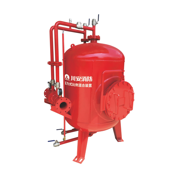
Vertical Foam Bladder Tank — Pressure Proportioning Device for Foam Suppression Systems
✓ PHY Series — 8 to 120 L/s
✓ 0.5–13.0 m³ Volume
✓ ±0.3% Mixing Accuracy
✓ No Electricity Required
✓ NFPA 11 Compliant
✓ GB / ISO 9001 / CE
The CA-FIRE PHY series vertical foam bladder tank is an upright pressure vessel that stores foam concentrate in an internal rubber bladder and delivers it to the system proportioner at the correct pressure and flow rate throughout a fire suppression discharge. The vertical orientation minimises floor footprint — making it the preferred vertical bladder tank configuration for facilities where floor space is at a premium but ceiling height is available: petrochemical plant rooms, refinery fire pump buildings, airport suppression equipment rooms and above-ground industrial fire protection installations. Flow rates from 8 L/s to 120 L/s, tank volumes customisable from 0.5 m³ to 13.0 m³, ±0.3% proportioning accuracy at 3% or 6% mixing ratio. No electricity required for proportioning.
Vertical Foam Bladder Tank — Technical Specifications
| Parameter | Specification |
|---|---|
| Product Type | Vertical Foam Bladder Tank — PHY Series Pressure Proportioning Device |
| Working Pressure Range | 0.6 – 1.2 MPa |
| Pressure Drop | ≤ 0.2 MPa |
| Strength Test Pressure | 1.5 MPa |
| Seal Test Pressure | 1.32 MPa |
| Tank Volume | 0.5 m³ – 13.0 m³ (customisable) |
| Main Pipe Diameter | DN80 – DN250 (customisable) |
| Proportioner Flow Range | 8 L/s – 120 L/s (customisable) |
| Foam Concentrate Mixing Ratio | 3% or 6% |
| Mixing Accuracy | ± 0.3% of rated ratio |
| Operating Temperature | 4 – 70 °C |
| Tank Body Material | Carbon steel, internal and external anti-corrosion coating |
| Bladder Material | Chemical-resistant rubber — compatible with AFFF, FFFP, protein foam, AR-AFFF |
| Certifications | GB standard · ISO 9001 · CE |
PHY Series — Model Parameters
Select the PHY model that matches your system design flow rate. Tank volume and pipe diameter are customisable — CA-FIRE’s engineering team provides project-specific hydraulic sizing at no charge.
| Model | Flow Rate (L/s) 3% ratio |
Flow Rate (L/s) 6% ratio |
Foam Liquid (L/s) 3% ratio |
Foam Liquid (L/s) 6% ratio |
Working Pressure (MPa) | Typical Tank Volume (m³) | Main Pipe Diameter |
|---|---|---|---|---|---|---|---|
| PHY 4 | 4 | 4 | 0.12 | 0.24 | 0.6–1.2 | 0.5–2.0 | DN80–DN100 |
| PHY 8 | 8 | 8 | 0.24 | 0.48 | 0.6–1.2 | 0.5–2.0 | DN80–DN100 |
| PHY 16 | 16 | 16 | 0.48 | 0.96 | 0.6–1.2 | 1.0–4.0 | DN100–DN150 |
| PHY 24 | 24 | 24 | 0.72 | 1.44 | 0.6–1.2 | 1.5–6.0 | DN125–DN150 |
| PHY 32 | 32 | 32 | 0.96 | 1.92 | 0.6–1.2 | 2.0–8.0 | DN150–DN200 |
| PHY 48 | 48 | 48 | 1.44 | 2.88 | 0.6–1.2 | 3.0–10.0 | DN200–DN250 |
| PHY 64 | 64 | 64 | 1.92 | 3.48 | 0.6–1.2 | 4.0–13.0 | DN200–DN250 |
| PHY 76 | 76 | 76 | 2.28 | 4.56 | 0.6–1.2 | 5.0–13.0 | DN200–DN250 |
| PHY 100 | 100 | 100 | 3.0 | 6.0 | 0.6–1.2 | 0.5–13.0 | DN80–DN250 |
* All dimensions customisable to project hydraulic design. Contact CA-FIRE for model selection and tank volume calculation.
How the Vertical Foam Bladder Tank Works
The PHY vertical foam bladder tank operates on a fully hydraulic displacement proportioning principle — no electricity, no diesel engine, no pneumatic supply required.
|
1
Standby — Bladder charged, system pressurised The rubber bladder is filled with foam concentrate. The annular space between bladder and tank shell is filled with pressurised water at system standby pressure. |
2
Activation — Water flows through the proportioner When the suppression system activates, water flows through the in-line proportioner. The venturi throat creates a controlled pressure differential that draws concentrate from the bladder into the water stream. |
|
3
Discharge — Hydraulic balance maintains ±0.3% accuracy As concentrate is displaced from the bladder, incoming water maintains equal pressure across the bladder wall. This self-regulating mechanism sustains ±0.3% mixing accuracy across the full flow range — without operator adjustment. |
4
Recharge — Unused concentrate fully preserved Any concentrate remaining after a partial discharge is in full-quality condition — the bladder prevented water contact throughout. Pump in fresh concentrate, repressurise, done. Ready for the next activation. |
Vertical Foam Bladder Tank — Key Features
|
📐 Minimal Floor Footprint — Maximum Headroom Utilisation The defining advantage of the vertical foam bladder tank is its compact floor plan. By stacking volumes vertically, the PHY series occupies significantly less floor area than an equivalent horizontal tank — in some configurations, less than half the footprint. Critical in fire pump rooms where floor space is shared with pumps, switchgear and pipework. When ceiling height is available but floor space is limited, the vertical bladder tank is the natural choice. Compact Plan · Ceiling Height Utilised |
🎯 ±0.3% Mixing Accuracy — Passive, Across Full Flow Range The PHY vertical foam bladder tank maintains proportioning accuracy within ±0.3% of the rated 3% or 6% mixing ratio across the full 8–120 L/s operating flow range — passively, without electronic controls or operator adjustment. The bladder’s hydraulic balance mechanism holds the ratio stable whether one sprinkler head or 50 are flowing simultaneously. Exceeds the ±30% tolerance permitted by NFPA 11. ±0.3% — Exceeds NFPA 11 Requirement |
|
🔒 Bladder Isolation — Long-Term Concentrate Preservation The rubber bladder physically separates foam concentrate from pressurised water throughout the storage period. Water cannot enter the concentrate side — the mechanism by which foam concentrate degrades in open-tank systems. Concentrate stored in a correctly maintained vertical foam bladder tank retains performance for the manufacturer’s full rated shelf life — typically 10–25 years. Ideal for systems that stand on standby for years between activations. 10–25yr Shelf Life · Reusable After Partial Discharge |
⚙️ Fully Customisable — Free Hydraulic Sizing Support Tank volume (0.5–13.0 m³), main pipe diameter (DN80–DN250), and proportioner flow capacity (8–120 L/s) are all adjustable — configured precisely for each project’s hydraulic model. No forced over-specification. CA-FIRE’s engineering team calculates the correct model, tank volume and pipe sizing per NFPA 11, NFPA 16 or GB standard discharge duration requirements — free of charge for every project inquiry. 0.5–13.0 m³ · DN80–DN250 · Free Sizing |
Applications — Where the Vertical Bladder Tank Is Specified
|
Petrochemical Plants & Refineries Process unit pump areas, storage tank bund areas and loading gantries requiring large-volume foam suppression in compact above-ground pump rooms. |
Oil & Fuel Storage Terminals Fixed and floating-roof storage tank protection requiring extended discharge durations up to 65 minutes per NFPA 11. Customisable volumes to 13.0 m³. |
Airports & Aircraft Hangars NFPA 409 aircraft hangar suppression systems requiring rapid 3% AFFF proportioning and large total foam volumes in hangar equipment room installations. |
|
Industrial Warehouses Warehouses storing flammable liquids and Class B materials where ceiling height is available and floor space adds direct storage revenue. |
Power Generation Facilities Turbine lube oil systems and fuel oil storage in power stations — suppression systems standing dormant for years, requiring reliable long-term concentrate preservation. |
Ports & Marine Terminals Fuel bunkering berths and cargo handling areas in coastal installations. Compact vertical footprint fits quayside pump rooms exposed to salt-air environments. |
Vertical vs. Horizontal Foam Bladder Tank — Selection Guide
Both configurations deliver identical ±0.3% proportioning performance. The selection is driven entirely by the physical dimensions of your installation space:
| Parameter | Vertical Bladder Tank (PHY) | Horizontal Bladder Tank (PHYM) |
|---|---|---|
| Floor footprint | ✓ Compact — minimal floor area | Larger — longer saddle-mounted footprint |
| Installed height | Higher — requires ceiling clearance | ✓ Low — fits restricted headroom |
| Above-ground pump rooms | ✓ Preferred — maximises floor space | Suitable |
| Underground / basement rooms | — Less suitable | ✓ Preferred — low profile fits |
| Shipboard installation | — Space constraints usually prohibit | ✓ Standard choice for vessels |
| Maximum flow rate | 8–120 L/s | 4–360 L/s (widest range) |
| Tank volume range | 0.5–13.0 m³ | 0.5–13.0 m³ |
| Proportioning accuracy | ±0.3% | ±0.3% |
| View product page | This page ↑ | Horizontal Tank → |
Installation Guidelines
Pre-Installation Checklist
Before positioning the vertical foam bladder tank, confirm the following: the PHY model, tank volume and pipe diameter match the system hydraulic design and applicable standard discharge duration; the installation space provides minimum clearances of 800 mm around the tank circumference and 1,000 mm above the tank top for bladder removal access; floor loading capacity is adequate for the filled tank weight (a 13.0 m³ PHY weighs approximately 14,000 kg when filled); all ancillary fittings are inspected for transit damage before installation.
Mechanical Installation
Set the vertical foam bladder tank on the prepared level foundation and anchor using the supplied base feet — do not rely on pipe connections to provide lateral stability. Connect water inlet, foam outlet, concentrate fill, vent, drain and safety valve connections per the system piping schematic. Use correct gasket materials at each flanged joint and torque all flange bolts evenly in a cross-pattern sequence to the specified torque value.
Bladder Filling & System Charging
Purge all air from the water side through the top vent valve before introducing concentrate. Fill the bladder slowly via the bladder fill valve — monitor the level indicator to avoid overfilling. Once at the correct charge volume, close the fill valve, pressurise the water side to system standby pressure, conduct a full leak check at all connections, and record the concentrate fill volume in the commissioning log.
Maintenance Schedule — NFPA 11 Compliance
| Frequency | Task |
|---|---|
| Monthly | Visual inspection of tank body, pipework and instrumentation for leaks, corrosion or physical damage. Verify pressure gauge readings on both water side and concentrate side — any unexplained differential pressure change warrants investigation for bladder leakage. Confirm all isolation valves are in the correct normal positions. |
| Quarterly | Verify concentrate level indicator against original fill record — investigate any unexplained volume reduction. Inspect all flanged joints and valve packing for signs of weeping. Test safety valve and air vent for correct manual operation. |
| Annual | Access the bladder through the top inspection manway — inspect for cuts, stiffening, blistering or chemical attack. Full pressure and seal test to 1.32 MPa. Sample the foam concentrate and test against manufacturer’s quality specification. Verify proportioning accuracy at system design flow rate. |
| Every 5–7 years | Preventive bladder replacement regardless of apparent condition. Full internal tank inspection and recoating if required. CA-FIRE supplies replacement bladders for all PHY series models with full installation guidance. |
Frequently Asked Questions
What is a vertical foam bladder tank and how does it differ from a horizontal model?
A vertical foam bladder tank is an upright pressure vessel that stores foam concentrate in an internal rubber bladder and proportions it into the fire suppression water supply when the system activates. The vertical orientation minimises floor footprint — preferable for above-ground fire pump rooms where ceiling height is available but floor space is constrained.
The horizontal foam bladder tank has a lower installed height and larger floor footprint — preferred for underground pump rooms, basement plant rooms, shipboard systems and low-ceiling buildings. Proportioning performance is identical in both orientations. See the horizontal foam bladder tank page for full details.
How is the correct PHY model and tank volume calculated?
Required volume = system design flow rate (L/s) × foam mixing ratio (3% or 6%) × required discharge duration (seconds). Discharge duration is set by the applicable standard — typically NFPA 11 (10 to 65 minutes depending on application) or GB standard equivalent.
CA-FIRE’s engineering team performs this calculation for every project inquiry and recommends the correct PHY model and tank volume at no charge. Contact us with your design flow rate, foam type and applicable standard.
How long does foam concentrate last inside a vertical foam bladder tank?
Concentrate stored in a correctly maintained vertical foam bladder tank retains its performance characteristics for the manufacturer’s rated shelf life — typically 10–25 years depending on concentrate type and storage temperature. The rubber bladder prevents water from contacting the concentrate throughout storage. Annual quality sampling of a concentrate specimen confirms whether stored concentrate remains within specification.
Does the vertical foam bladder tank require electricity to operate?
No. The PHY vertical foam bladder tank operates entirely on water supply pressure — no electricity, no diesel engine and no pneumatic supply is required for proportioning. This makes it suitable for hazardous area classifications where electrical equipment must be minimised, and for remote locations without reliable power infrastructure.
Can the tank be recharged after a partial discharge?
Yes. Concentrate remaining in the bladder after a partial discharge is in full-quality condition — the bladder prevented water contact throughout. Connect a concentrate transfer pump to the bladder fill connection, refill to the original charge volume, repressurise the water side, and the system is back to standby. Partial-discharge rechargeability significantly reduces operational costs compared to atmospheric proportioning systems, where water-contacted concentrate must be discarded.
What foam concentrates are compatible with the CA-FIRE vertical foam bladder tank?
The PHY series is compatible with AFFF, FFFP, protein foam, alcohol-resistant foam (AR-AFFF) and synthetic foam concentrates at 3% and 6% mixing ratios. For fluorine-free foam alternatives, bladder elastomer compatibility with the specific concentrate formulation should be confirmed with CA-FIRE’s technical team at the time of specification.
Why Specify CA-FIRE Vertical Foam Bladder Tanks
|
✓ Factory Tested — Every Unit Every PHY vertical foam bladder tank is hydrostatically tested to 1.5 MPa and proportioning accuracy verified to ±0.3% before despatch. Full test certification provided for authority submission — no site testing surprises. |
✓ Free Hydraulic Sizing Support CA-FIRE’s engineering team calculates the correct PHY model, tank volume and pipe diameter for your project — per NFPA 11, NFPA 16 or GB standard discharge duration requirements. No charge for every project inquiry. |
|
✓ ISO 9001 · GB Certified · 50+ Countries ISO 9001 certified manufacturing, GB 5135 standard certification, and over a decade supplying vertical bladder tank systems to petrochemical, aviation, marine and industrial fire suppression projects globally. |
✓ Long-Term Parts Availability Replacement bladders, proportioner cartridges and ancillary components held in stock for all current and legacy PHY series models. No obsolescence risk on long-lifecycle fire protection assets. |
Related Products
|
PHYM Series · Low Headroom Horizontal Foam Bladder Tank Low-profile configuration for underground pump rooms, basement plant rooms and shipboard suppression. Flow range 4–360 L/s — widest in the CA-FIRE range. |
Mobile · First Response Portable Foam Fire Extinguishing System Self-contained mobile foam suppression unit — no fixed pipework required. Wheeled or skid-mounted. For first response and temporary protection. |
Full Range · All Models Foam Bladder Tank — Category Overview Compare all CA-FIRE foam bladder tank configurations — horizontal, vertical and portable — with a full specification comparison table and selection guide. |
Get a Quote — Vertical Foam Bladder Tank
PHY Series · 0.5–13.0 m³ · 8–120 L/s · 3% or 6% · NFPA 11 · Free Hydraulic Sizing · Factory Direct
| Product Name | Specification Model | Working Pressure Range (MPa) | Flow Rate Range (L/s) | Foam Mixing Ratio | Tank Volume (m³) | Inlet/Outlet Connection | Pressure Drop (MPa) | Foam Bladder Tank Price Range (USD) |
|---|---|---|---|---|---|---|---|---|
| Vertical Pressure Proportioning Mixing Device (with Foam Bladder Tank) | PHY 8 | 0.6~1.2 | 8 | 3% / 6% | 0.5~13.0 (Customizable) | Flange (DN80~DN250, Customizable) | ≤0.2 | 2,800 – 4,500 |
| PHY 16 | 0.6~1.2 | 16 | 3% / 6% | 0.5~13.0 (Customizable) | Flange (DN80~DN250, Customizable) | ≤0.2 | 3,500 – 5,200 | |
| PHY 24 | 0.6~1.2 | 24 | 3% / 6% | 0.5~13.0 (Customizable) | Flange (DN80~DN250, Customizable) | ≤0.2 | 4,200 – 6,000 | |
| PHY 32 | 0.6~1.2 | 32 | 3% / 6% | 0.5~13.0 (Customizable) | Flange (DN80~DN250, Customizable) | ≤0.2 | 5,000 – 7,000 | |
| PHY 48 | 0.6~1.2 | 48 | 3% / 6% | 0.5~13.0 (Customizable) | Flange (DN80~DN250, Customizable) | ≤0.2 | 6,500 – 8,500 | |
| PHY 64 | 0.6~1.2 | 64 | 3% / 6% | 0.5~13.0 (Customizable) | Flange (DN80~DN250, Customizable) | ≤0.2 | 8,000 – 10,000 |