
Signal Gate Valve for Fire Protection Systems
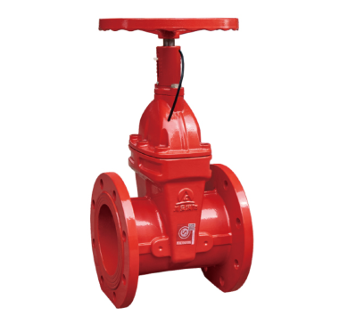
A signal gate valve is a supervised, indicating gate valve designed specifically for fire protection pipelines. Unlike a standard gate valve, it incorporates a built-in tamper switch that sends real-time open/close status signals to the fire alarm control panel (FACP) — ensuring that any unauthorized valve operation is detected immediately and the system remains in a ready state at all times.
CA-FIRE’s signal gate valve series meets NFPA 13, GB 15930 and CE requirements, and is trusted by fire protection engineers across high-rise buildings, industrial facilities, commercial complexes and public infrastructure worldwide.
Technical Specifications
The CA-FIRE signal gate valve is engineered to perform reliably under the demanding pressure and flow conditions of modern fire suppression systems.
| Parameter | Specification |
|---|---|
| Product Model | ZSXZF4-Q-50-300-16 (Flange) / ZSXZF8-Q-50-250-16 (Grooved) |
| Nominal Pressure | 1.6 MPa (PN16) |
| Nominal Diameter | DN50–DN300 (Flange) / DN50–DN250 (Grooved) |
| Strength Test Pressure | 6.4 MPa |
| Seal Test Pressure | 3.2 MPa |
| Applicable Medium | Water, foam fire suppression mixture |
| Medium Temperature | 4–70 °C |
| Switch Contact Capacity | DC 24V / 0.5A |
| Connection Method | Flanged / Grooved (Victaulic-compatible) |
| Stem Design | Non-Rising Stem (NRS) / Rising Stem (OS&Y) |
| Signal Transmission Delay | < 0.5 seconds |
| Certifications | GB 15930, ISO 9001, CE |
Structural Length by Nominal Diameter
| Nominal Diameter | Flange Type (mm) | Grooved Type (mm) |
|---|---|---|
| DN50 | 185 | 150 |
| DN65 | 190 | 160 |
| DN80 | 200 | 175 |
| DN100 | 228 | 185 |
| DN125 | 255 | 205 |
| DN150 | 270 | 212 |
| DN200 | 290 | 248 |
| DN250 | 330 | 263 |
| DN300 | 358 | — |
Key Features
Real-Time Tamper Switch Signal Feedback
The integrated limit switch detects valve position and transmits a DC 24V electrical signal to the fire alarm control panel in under 0.5 seconds. Any attempt to close or partially close the valve triggers an immediate supervisory alarm at the FACP, allowing facility managers to investigate and restore system integrity before an emergency occurs. This tamper detection capability is a core requirement under NFPA 13 and equivalent international fire codes.
Dual Stem Design: NRS and OS&Y
The signal gate valve is available in two stem configurations to suit different installation environments:
- Non-Rising Stem (NRS): The stem does not extend beyond the bonnet when operated, minimising the installation footprint. A clearly marked dial indicator shows the valve’s open/close degree at a glance. Ideal for valve pits, underground installations and areas with limited overhead clearance.
- Rising Stem (OS&Y): The stem rises visibly as the valve opens, providing immediate visual confirmation of valve position without the need for any indicator device. Required in many jurisdictions for above-ground fire protection applications per NFPA 13.
Reliable Bi-Directional Sealing
A multi-layer sealing structure — incorporating high-quality elastomeric gaskets and hardened valve seat surfaces — ensures a bubble-tight shut-off in both flow directions. Sealing components are rated for temperatures up to 70°C and resist aging, wear and chemical degradation, maintaining performance across the valve’s full service life.
Full-Bore Flow Path
The unobstructed full-bore design eliminates internal restrictions, minimising pressure drop across the valve when fully open. This is critical in fire suppression systems, where maintaining design flow rates and residual pressures at sprinkler heads can mean the difference between effective suppression and system failure.
Flexible Connection Options
Both flanged (ANSI B16.5 / DIN 2501) and grooved (Victaulic-compatible) end connections are available, enabling straightforward integration into new or existing fire protection pipelines. The low operating torque handwheel design allows the valve to be opened or closed quickly — even while wearing fire protection gloves.
Applications
Automatic Fire Sprinkler Systems
Installed on wet-pipe, dry-pipe and pre-action sprinkler system risers and branch mains, the signal gate valve provides the mandatory supervisory monitoring required by NFPA 13. The tamper switch ensures that any partial or full valve closure during normal operation is reported to the FACP immediately, preventing undetected system impairment.
Fire Hydrant and Standpipe Systems
Used as a control valve on fire hydrant supply mains and Class I, II and III standpipe systems. The real-time signal feedback allows building operators and fire departments to confirm that supply valves are fully open and the system is ready for use during a fire event.
High-Rise Buildings
In high-rise buildings, signal gate valves are installed at each floor zone valve and at main riser isolations. Central building management systems (BMS) or fire alarm control panels monitor all valve positions simultaneously, enabling rapid identification of any impaired zone.
Industrial and Petrochemical Facilities
Factories, warehouses and petrochemical plants require highly reliable fire water supply systems. The robust cast iron or stainless steel construction of the CA-FIRE signal gate valve withstands demanding industrial environments, while the supervisory signal function ensures fire system integrity is continuously monitored.
Commercial Complexes and Public Infrastructure
Shopping centres, hotels, airports, hospitals and schools rely on CA-FIRE signal gate valves to provide continuous supervisory monitoring of their fire suppression systems, protecting occupants and meeting the requirements of local fire authority inspections.
Installation Guidelines
Pre-Installation Checklist
- Verify the valve nominal diameter and pressure rating match the pipeline design requirements.
- Confirm the installation space provides a minimum 300 mm clearance on all sides for operation and maintenance access.
- Inspect the valve body, signal sensor, limit switch and wiring for any transit damage before installation.
- Ensure the pipeline is flushed and free of debris that could damage the valve seat or sealing surfaces.
Flanged Connection Installation
Align the valve flange faces with the mating pipeline flanges, ensuring the flow direction arrow on the valve body matches the intended flow direction. Insert the correct gasket material between flanges and torque all bolts evenly in a cross pattern to the manufacturer’s specified torque value. Uneven bolt torque is the most common cause of flange leakage.
Grooved Connection Installation
Clean the pipe groove and valve groove interface. Position the gasket and grooved coupling housing, then tighten the coupling bolts evenly until the housing pads make firm metal-to-metal contact. Do not over-torque, as this can deform the gasket and reduce sealing performance.
Signal Wiring
Connect the tamper switch signal wires to the fire alarm control panel supervisory zone according to the panel manufacturer’s wiring diagram. Route all signal wiring in a metallic conduit to protect against mechanical damage and electromagnetic interference. After wiring, test the signal by manually operating the valve and confirming that the FACP registers the correct supervisory alarm and restoral.
Post-Installation Testing
- Pressure test to 3.2 MPa and hold for the required duration — check for leaks at the valve body, flanges/couplings and signal penetrations.
- Fully open and fully close the valve and confirm correct signal transmission to the FACP at both end positions.
- Confirm the valve position indicator (NRS dial or OS&Y stem) accurately reflects the valve’s actual open/close state.
- Record the installation date, test results and tester’s name in the building’s fire protection system logbook.
Maintenance Schedule
Routine maintenance of the signal gate valve is required to comply with NFPA 25 (Inspection, Testing and Maintenance of Water-Based Fire Protection Systems) and equivalent local standards.
Monthly — Visual Inspection
- Check the valve body for external corrosion, mechanical damage or leaks.
- Confirm the valve is in the fully open position and secured with a lock or tamper-seal.
- Verify the signal indicator or FACP supervisory zone shows a normal status.
- Check signal wiring conduit for physical damage.
Quarterly — Operational Test
- Partially close and reopen the valve; confirm the FACP registers a supervisory alarm when closing and a restoral when fully reopened.
- Check the handwheel and stem for smooth, jam-free operation. Apply stem lubricant if any stiffness is detected.
- Inspect and tighten any loose flange bolts or coupling fasteners.
Annual — Full Inspection and Test
- Disassemble the bonnet and inspect the valve stem, stem nut and sealing components for wear or corrosion.
- Conduct a full pressure and seal test (3.2 MPa) and record results.
- Calibrate the tamper switch and limit switch; replace if response time exceeds 0.5 seconds.
- Replace elastomeric sealing gaskets and packing as a preventive measure (recommended every 1–2 years).
- Lubricate all moving components — stem, stem nut, handwheel spindle — with a water-resistant, fire-system approved lubricant.
Why Specify CA-FIRE Signal Gate Valves?
CA-FIRE is a dedicated fire protection equipment manufacturer with integrated R&D, production, quality control and after-sales support. Every signal gate valve leaving our facility has passed:
- Hydrostatic pressure testing to 6.4 MPa (4× working pressure)
- Seal integrity testing to 3.2 MPa
- Signal response time verification (< 0.5 second requirement)
- Full dimensional inspection against GB 15930 and customer-specified standards
Our products are installed in national key infrastructure projects, commercial high-rises, industrial complexes and residential developments across more than 50 countries. We offer flanged and grooved configurations, non-rising and rising stem designs, and custom specifications for OEM customers — all backed by a comprehensive technical support team available for installation guidance, commissioning assistance and troubleshooting.
Frequently Asked Questions
What is a signal gate valve?
A signal gate valve is a type of gate valve fitted with a built-in limit switch (tamper switch) that automatically sends an electrical signal to the fire alarm control panel whenever the valve is moved from its fully open position. This supervisory function ensures that any partial or complete valve closure is detected and reported immediately — a mandatory requirement for control valves in automatic fire sprinkler systems under NFPA 13 and similar codes.
What is the difference between a signal gate valve and a standard gate valve?
A standard gate valve simply opens or closes the flow path without any feedback mechanism. A signal gate valve adds a tamper switch and signal transmission circuit that monitors valve position continuously. In fire protection applications, using a standard gate valve without supervisory monitoring on a sprinkler system control valve is a code violation in most jurisdictions.
What does NFPA 13 require for signal gate valves?
NFPA 13 requires that all control valves in sprinkler systems be supervised — meaning any movement of the valve from its normal open position must send a supervisory signal to a constantly attended location or trigger a local alarm. A signal gate valve with a tamper switch satisfies this requirement when correctly wired to a fire alarm control panel.
NRS vs OS&Y — which should I specify?
Specify Non-Rising Stem (NRS) where installation headroom is limited, such as in valve pits, underground vaults or ceiling-mounted applications. Specify OS&Y (Outside Screw and Yoke) for above-ground installations where direct visual confirmation of valve position is desirable, or where local codes specifically require a rising-stem indicating valve.
What sizes are available?
CA-FIRE signal gate valves are available in DN50 through DN300 for flanged-end models and DN50 through DN250 for grooved-end models, covering the majority of fire protection pipeline sizes encountered in building and industrial applications.
Get a Quote
For pricing, technical drawings or project-specific specifications, contact CA-FIRE today. Our engineering team responds within one business day.
- Email: sales@ca-fire.com
- Mobile / WhatsApp: +86 13400715622
- WeChat: 404863577
- Website: www.ca-fire.com
Explore CA-FIRE’s complete fire protection product range: Gate Valve Series · Fire Alarm Valves · Fire Sprinkler Heads
For fire protection system design standards and best practices, visit the National Fire Protection Association (NFPA).
| Parameter | Specification |
|---|---|
| Product Model | ZSXZF4-Q-50-300-16 (Flange) / ZSXZF8-Q-50-250-16 (Grooved) |
| Nominal Pressure | 1.6 MPa (PN16) |
| Nominal Diameter | DN50–DN300 (Flange) / DN50–DN250 (Grooved) |
| Strength Test Pressure | 6.4 MPa |
| Seal Test Pressure | 3.2 MPa |
| Applicable Medium | Water, foam fire suppression mixture |
| Medium Temperature | 4–70 °C |
| Switch Contact Capacity | DC 24V / 0.5A |
| Connection Method | Flanged / Grooved (Victaulic-compatible) |
| Stem Design | Non-Rising Stem (NRS) / Rising Stem (OS&Y) |
| Signal Transmission Delay | < 0.5 seconds |
| Certifications | GB 15930, ISO 9001, CE |
| Nominal Diameter | Flange Type (mm) | Grooved Type (mm) |
|---|---|---|
| DN50 | 185 | 150 |
| DN65 | 190 | 160 |
| DN80 | 200 | 175 |
| DN100 | 228 | 185 |
| DN125 | 255 | 205 |
| DN150 | 270 | 212 |
| DN200 | 290 | 248 |
| DN250 | 330 | 263 |
| DN300 | 358 | — |