
Resilient Wedge Gate Valve — Grooved End Fire Protection Design
A resilient wedge gate valve is a fire protection isolation valve in which the closing element — the wedge — is fully encapsulated in EPDM rubber rather than machined from bare metal. When the handwheel is turned to close, the rubber-coated wedge compresses against the precision valve seats, creating a watertight seal that accommodates minor seat irregularities, thermal movement and the small dimensional variations inherent in cast valve bodies. The result is consistent, bubble-tight shut-off at low operating torque — achieved reliably across the full service life of the valve without seat grinding, lapping or adjustment.
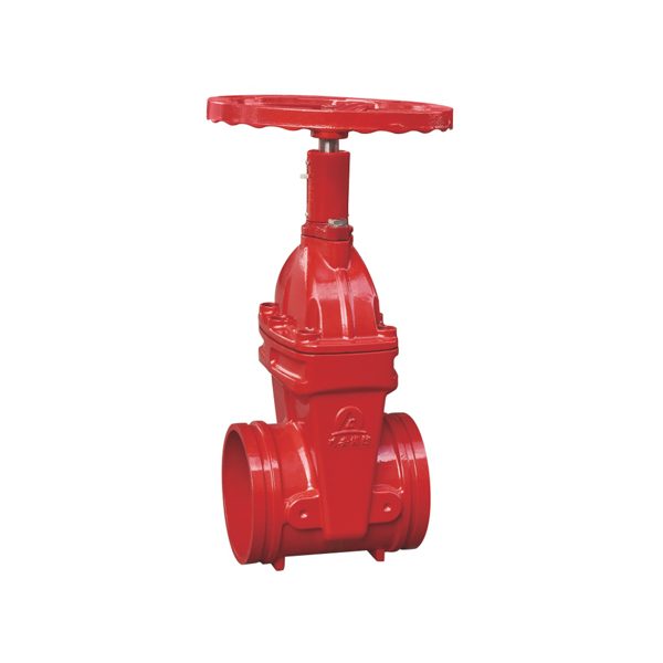
CA-FIRE’s grooved end resilient wedge gate valve (Model: ZSZF8-Q-50~250-16) brings this proven sealing technology to a lightweight, Victaulic-compatible grooved body — delivering fast installation, compact dimensions and long-term sealing reliability in a single product. Available in DN50–DN250, it is engineered for fire sprinkler systems, fire hydrant mains and standpipe systems in commercial buildings, industrial facilities and infrastructure projects worldwide.
Resilient Wedge Gate Valve Technical Specifications
| Parameter | Specification |
|---|---|
| Product Model | ZSZF8-Q-50~250-16 |
| Valve Type | Resilient Wedge Gate Valve — Grooved End, Non-Rising Stem |
| Nominal Pressure | 1.6 MPa (PN16) |
| Nominal Diameter | DN50–DN250 |
| Strength Test Pressure | 6.4 MPa |
| Seal Test Pressure | 3.2 MPa |
| Applicable Medium | Water, foam fire suppression mixture |
| Medium Temperature | 4–70 °C |
| Connection Method | Grooved ends — Victaulic IPS compatible |
| Stem Design | Non-Rising Stem (NRS) — fixed height, dial position indicator |
| Wedge Material | Ductile iron fully encapsulated with EPDM rubber |
| Body Material | Ductile iron, fusion-bonded epoxy coated inside and out |
| Certifications | GB 12736, ISO 9001, CE |
Structural Length by Nominal Diameter
| Nominal Diameter | Structural Length (mm) |
|---|---|
| DN50 | 150 |
| DN65 | 160 |
| DN80 | 175 |
| DN100 | 185 |
| DN125 | 205 |
| DN150 | 212 |
| DN200 | 248 |
| DN250 | 263 |
Resilient Wedge Gate Valve Key Features
EPDM-Encapsulated Resilient Wedge — Zero-Leakage Shut-Off
The heart of the resilient wedge gate valve is its fully encapsulated ductile iron wedge. The EPDM rubber coating wraps the entire wedge surface — not just the seating faces — protecting the underlying metal from corrosion and providing a compliant sealing surface that conforms precisely to the valve seat geometry under closing force. This encapsulation eliminates the metal-to-metal contact of older solid wedge designs, removing the risk of seat scoring, corrosion welding and the hydraulic locking that can prevent solid wedge valves from reopening after extended closure. The result is zero-leakage shut-off that can be achieved consistently, valve after valve, without site-by-site seat adjustment.
Grooved End Connection — Lightweight and Tool-Friendly
The Victaulic IPS-compatible grooved ends replace heavy bolted flanges with a simple two-bolt mechanical coupling, reducing the installed weight of the resilient wedge gate valve by up to 30% compared to a flanged equivalent. Each grooved joint can be assembled by a single installer using a standard socket wrench in under two minutes — no gasket alignment, no flange drilling, no torque wrench calibration. For fire protection contractors working across multiple floors or in confined riser enclosures, this weight and installation time saving translates directly into programme and cost efficiency.
Non-Rising Stem with Dial Indicator
The non-rising stem design maintains a fixed installed height regardless of valve position, making the resilient wedge gate valve suitable for locations with restricted overhead clearance — basement plant rooms, ceiling-void installations and dense pipe rack environments where a rising stem would be impractical. The bonnet-mounted dial indicator provides a clear visual display of the valve’s open/close position, satisfying NFPA 13’s indicating valve requirement without the need for an electronic tamper switch. For applications where electronic supervisory monitoring is additionally required, the grooved signal gate valve model (ZSXZF8-Q-50~250-16) provides both dial indication and DC 24V tamper switch output.
Full-Bore Flow Path with Minimal Friction Loss
Opening the resilient wedge gate valve completely retracts the wedge into the valve body cavity, leaving a completely clear, full-bore flow path through the valve. There are no internal obstructions, partial restrictions or flow direction changes — water passes straight through as if the valve were not there. In fire protection hydraulic calculations, the pressure drop across a fully open resilient wedge gate valve is typically expressed as an equivalent pipe length of just 0.3–0.5 metres — negligible compared to the friction losses in the pipeline itself. This full-bore characteristic makes the resilient wedge gate valve the most hydraulically efficient isolation valve option for fire suppression systems.
Fusion-Bonded Epoxy Coating for Long Service Life
Both the internal flow surfaces and the external body of the resilient wedge gate valve receive a factory-applied fusion-bonded epoxy coating. The epoxy is electrostatically applied after shot-blasting and thermally cured to achieve a uniform, pinhole-free film that bonds permanently to the ductile iron substrate. This coating system resists corrosion from stagnant fire water, chlorine treatment chemicals and the humid environments of fire pump rooms and riser enclosures, protecting the valve body throughout its design service life of 25+ years.
Resilient Wedge Gate Valve Applications
[IMAGE: resilient wedge gate valve grooved installed sprinkler system riser — CA-FIRE fire protection] [IMAGE ALT TEXT: resilient wedge gate valve installed on fire sprinkler system riser — CA-FIRE grooved ZSZF8]
Zone Isolation on Fire Sprinkler Systems
Installed as zone control and sectional isolation valves on wet-pipe, dry-pipe and pre-action automatic sprinkler systems, the resilient wedge gate valve provides the reliable on/off isolation required for system maintenance, impairment management and zone testing. The full-bore flow path ensures no reduction in system hydraulic performance when the valve is open, while the resilient wedge delivers the positive shut-off needed to isolate zones cleanly for maintenance work. The dial position indicator satisfies NFPA 13’s indicating valve requirement for sprinkler control valves.
Riser and Branch Main Isolation
Used as riser isolation and branch main sectional valves throughout multi-storey buildings, the lightweight grooved body of the resilient wedge gate valve is particularly well suited to installation in riser enclosures and valve cupboards where handling space is restricted. The grooved connection allows the valve to be removed from the line for inspection or replacement without cutting the pipe — the two coupling bolts are removed, the valve slides out and a replacement slides back in, minimising system downtime during maintenance.
Fire Hydrant Branch Connections
Specified as the isolation valve on fire hydrant branch connections from fire water mains, the resilient wedge gate valve’s low operating torque and positive shut-off characteristics allow responding personnel to quickly close off a defective hydrant branch without impacting the rest of the fire water supply network. The EPDM wedge resists the intermittent wetting and drying cycles typical of outdoor hydrant branch connections without deteriorating.
Mechanical Plant Rooms and Basement Installations
In mechanical plant rooms, basement fire pump rooms and other below-ground locations where pipeline density is high and working space is limited, the compact grooved body and non-rising stem of the resilient wedge gate valve minimise both the lateral and vertical space the valve occupies. The absence of protruding flange plates and bolt heads reduces the risk of accidental mechanical damage during maintenance operations in congested areas.
Industrial Fire Water Systems
In industrial facilities — manufacturing plants, logistics warehouses, food processing facilities — where fire water distribution pipelines traverse large floor areas with multiple isolation points, the resilient wedge gate valve’s combination of fast grooved installation and low-maintenance EPDM sealing makes it the cost-effective specification for multiple valve locations. The valve’s compatibility with foam fire suppression mixtures extends its application to facilities where foam and water systems share common pipework.
Why EPDM Matters — Resilient Wedge vs. Metal Wedge Gate Valves
Understanding the difference between resilient wedge and solid metal wedge designs helps engineers specify the right valve for each application.
A solid metal wedge gate valve relies on precision-machined metal-to-metal contact between the wedge faces and the valve seats to achieve shut-off. Over time, the seating surfaces are vulnerable to corrosion pitting, scale deposits and minor mechanical damage — any of which can cause leakage. Re-seating a worn metal wedge valve typically requires lapping or professional refurbishment.
The resilient wedge gate valve eliminates these vulnerabilities. The EPDM coating on the wedge is chemically inert to chlorinated water and foam concentrates, physically resilient to the minor impacts and vibrations of an operating pipeline system, and dimensionally compliant enough to seal against seats that would cause a metal wedge to leak. When the EPDM coating eventually approaches end of life — typically after 15–25 years of service — the wedge assembly can be replaced without replacing the entire valve body, significantly reducing the long-term maintenance cost of the installation.
Installation Guidelines
Pre-Installation Checklist
- Confirm the resilient wedge gate valve nominal diameter matches the pipeline and that the grooved end dimensions comply with IPS standards.
- Check overhead clearance — while the non-rising stem requires no stem travel space, confirm the handwheel can be fully rotated without obstruction.
- Inspect the EPDM wedge, grooved faces and body coating for any transit damage before installation.
- Verify the pipeline has been pressure-tested and flushed clean — debris in the line can damage the EPDM wedge surface on first closure.
Grooved Joint Assembly
Lubricate the coupling gasket with the manufacturer’s approved lubricant — use only EPDM-compatible lubricant; petroleum-based products will damage the gasket. Slide the gasket centrally over the pipe end and position the resilient wedge gate valve between the pipe ends. Fit the coupling housing halves into the grooves on both the valve end and the pipe end, insert the coupling bolts and tighten evenly in an alternating sequence until the coupling housing pads achieve firm metal-to-metal contact. Check both grooved joints for uniform gasket seating before pressurising.
First Operation After Installation
Open the resilient wedge gate valve slowly to full open before pressure testing to allow the system to fill gradually and prevent water hammer. After filling, close the valve fully and confirm zero leakage at the body and grooved joints under system pressure. Reopen to full open. Confirm the dial indicator correctly shows the fully open position, then lock the valve open with an approved locking device.
Post-Installation Pressure Test
Conduct a hydrostatic pressure test to 3.2 MPa — hold for the required test duration and check for leakage at the valve body, grooved couplings and bonnet. Any leakage at the grooved joints should be corrected by checking gasket seating and re-torquing the coupling bolts before retesting. Document all test pressures, hold times and results in the fire protection system commissioning record.
Maintenance Schedule
Maintenance of the resilient wedge gate valve in fire protection service must comply with NFPA 25 and applicable local authority inspection requirements.
Monthly — Visual Inspection
- Confirm the dial indicator shows fully open position.
- Check the valve is locked or sealed in the open position.
- Inspect the body, grooved couplings and bonnet for leaks, corrosion or physical damage.
- Verify no debris or mechanical damage to the EPDM wedge area is visible through the pipeline if the system is drained.
Quarterly — Exercise and Check
- Operate the resilient wedge gate valve through its full open-close-open travel to prevent stem binding and confirm smooth, low-torque operation throughout full travel.
- Check grooved coupling bolts for looseness — a single re-torque may be required in the first quarter after installation as the gasket beds in.
- Inspect the grooved coupling gaskets for any visible extrusion or displacement at the joint line.
Annual — Full Inspection
- Remove the resilient wedge gate valve from the line using the grooved coupling quick-release method and inspect the EPDM wedge surface for cuts, compression set, chemical attack or mechanical damage.
- Inspect the stem, stem nut and bonnet sealing for wear.
- Conduct a bench pressure and seat test to 3.2 MPa and record results.
- Replace the EPDM wedge assembly preventively every 10–15 years, or earlier if inspection reveals deterioration.
- Replace grooved coupling gaskets every 5 years as a preventive measure.
Resilient Wedge Gate Valve — Frequently Asked Questions
What makes a resilient wedge gate valve different from other gate valve types?
The defining feature of a resilient wedge gate valve is its EPDM rubber-encapsulated closing element. The rubber coating provides a compliant, corrosion-resistant sealing surface that achieves watertight shut-off at lower closing torques and with greater tolerance for seat surface imperfections than metal wedge designs. This makes the resilient wedge gate valve more reliable in long-term fire protection service — where valves may remain in the open position for years between test operations — and easier to reopen after extended closure.
Does the grooved resilient wedge gate valve meet NFPA 13 requirements?
Yes. The CA-FIRE grooved resilient wedge gate valve satisfies NFPA 13’s requirement for an indicating-type control valve through its bonnet-mounted dial indicator, which visually displays valve position at all times. For applications where electronic supervisory monitoring is additionally required by the authority having jurisdiction, the grooved signal gate valve model (ZSXZF8-Q-50~250-16) provides DC 24V tamper switch output in addition to the dial indicator.
What is the difference between this valve and the grooved signal gate valve?
Both are grooved end, non-rising stem resilient wedge gate valves with the same hydraulic performance and dimensional footprint. The key difference is that the signal gate valve model includes a factory-fitted DC 24V tamper switch for electronic supervisory monitoring of valve position at the fire alarm control panel — required by NFPA 13 for all sprinkler system control valves unless the valve is supervised by another approved method. The resilient wedge gate valve without the tamper switch is used in applications where visual dial indication alone is sufficient, or where supervisory monitoring is provided by a separate post indicator valve assembly.
Is EPDM compatible with foam fire suppression concentrates?
Yes. EPDM (Ethylene Propylene Diene Monomer) rubber has excellent chemical resistance to water, aqueous film-forming foam (AFFF), protein foam and most film-forming fluoroprotein (FFFP) concentrates used in fire suppression systems. Confirm specific compatibility with CA-FIRE’s technical team when specifying for foam system applications, particularly with high-concentration or fluorine-free foam formulations.
What grooved coupling standard is used?
The CA-FIRE resilient wedge gate valve is machined to IPS (Iron Pipe Size) grooved standard, compatible with Victaulic and all major IPS-standard grooved coupling manufacturers across the DN50–DN250 size range. Always confirm the pipe outside diameter and groove standard with your coupling supplier before installation.
Why Specify CA-FIRE’s Resilient Wedge Gate Valve?
CA-FIRE engineers the resilient wedge gate valve to perform reliably across its full 25+ year design life in fire protection service. Every valve undergoes factory hydrostatic pressure testing to 6.4 MPa, seat leak testing to 3.2 MPa and full dimensional inspection against GB 12736 before leaving our manufacturing facility. The EPDM wedge encapsulation is applied and cured under controlled factory conditions — not a field-applied coating — ensuring consistent coverage, bond strength and chemical resistance across every valve in the production run.
With ISO 9001 certified manufacturing and GB 12736 product certification, our resilient wedge gate valve is accepted by fire protection authorities across more than 50 countries. The grooved DN50–DN250 range pairs seamlessly with CA-FIRE’s grooved signal gate valve for applications requiring electronic tamper switch monitoring, and with the flanged resilient wedge range for larger diameter primary connections at DN300 and above.
Get a Quote
Contact CA-FIRE for pricing, technical drawings, project specifications or OEM enquiries. Our engineering team responds within one business day.
- Email: sales@ca-fire.com
- Mobile / WhatsApp: +86 13400715622
- WeChat: 404863577
- Website: www.ca-fire.com
Related products: Grooved Signal Gate Valve · Flanged NRS Gate Valve · OS&Y Gate Valve · Gate Valve Series · Fire Alarm Valves
For resilient wedge gate valve inspection and maintenance requirements in fire protection service, refer to NFPA 25.
| Parameter | Specification |
|---|---|
| Product Model | ZSZF8-Q-50~250-16 |
| Valve Type | Resilient Wedge Gate Valve — Grooved End, Non-Rising Stem |
| Nominal Pressure | 1.6 MPa (PN16) |
| Nominal Diameter | DN50–DN250 |
| Strength Test Pressure | 6.4 MPa |
| Seal Test Pressure | 3.2 MPa |
| Applicable Medium | Water, foam fire suppression mixture |
| Medium Temperature | 4–70 °C |
| Connection Method | Grooved ends — Victaulic IPS compatible |
| Stem Design | Non-Rising Stem (NRS) — fixed height, dial position indicator |
| Wedge Material | Ductile iron fully encapsulated with EPDM rubber |
| Body Material | Ductile iron, fusion-bonded epoxy coated inside and out |
| Certifications | GB 12736, ISO 9001, CE |
| Nominal Diameter | Structural Length (mm) |
|---|---|
| DN50 | 150 |
| DN65 | 160 |
| DN80 | 175 |
| DN100 | 185 |
| DN125 | 205 |
| DN150 | 212 |
| DN200 | 248 |
| DN250 | 263 |