
OS&Y Gate Valve for Fire Protection Systems — Rising Stem Design
The OS&Y gate valve, or Outside Screw and Yoke gate valve, is a rising stem gate valve designed specifically for fire protection pipelines. As the handwheel is turned, the threaded stem rises visibly above the bonnet, providing unmistakable confirmation that the valve is open and the fire suppression system is fully operational. This clear visual indication makes the OS&Y gate valve the preferred control valve for sprinkler systems, standpipe systems and fire hydrant mains under NFPA 13 and equivalent international codes.
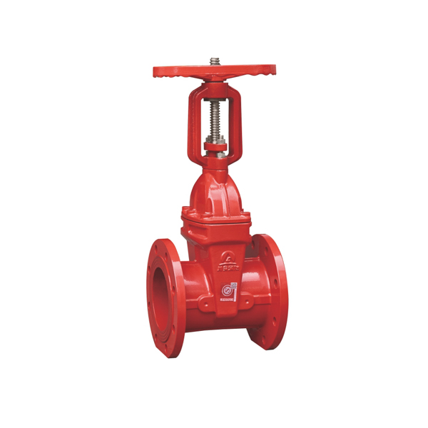
CA-FIRE’s OS&Y gate valve (Model: ZSZF4-Q-50~400-16-M) is engineered for reliable long-term service in the most demanding fire protection environments, from high-rise buildings and industrial facilities to commercial complexes and public infrastructure worldwide.
OS&Y Gate Valve Technical Specifications
[IMAGE: OS&Y gate valve DN50-DN400 flanged fire protection — CA-FIRE ZSZF4-Q-50~400-16-M] [IMAGE ALT TEXT: OS&Y gate valve DN50-DN400 flanged fire protection — CA-FIRE ZSZF4-Q-50~400-16-M]
The CA-FIRE OS&Y gate valve is built to perform reliably under the demanding pressure and flow conditions of modern fire suppression systems. Full specifications are listed below.
| Parameter | Specification |
|---|---|
| Product Model | ZSZF4-Q-50~400-16-M |
| Valve Type | OS&Y Gate Valve (Rising Stem — Outside Screw and Yoke) |
| Nominal Pressure | 1.6 MPa (PN16) |
| Nominal Diameter | DN50–DN400 |
| Strength Test Pressure | 6.4 MPa |
| Seal Test Pressure | 3.2 MPa |
| Applicable Medium | Water, foam fire suppression mixture |
| Medium Temperature | 4–70 °C |
| Connection Method | Flanged (ANSI B16.1 / DIN 2501) |
| Stem Design | Rising Stem — Outside Screw and Yoke (OS&Y) |
| Wedge Type | Resilient wedge, rubber-encapsulated |
| Certifications | GB 12736, ISO 9001, CE |
Structural Length by Nominal Diameter
| Nominal Diameter | Structural Length (mm) |
|---|---|
| DN50 | 185 |
| DN65 | 190 |
| DN80 | 200 |
| DN100 | 228 |
| DN125 | 255 |
| DN150 | 270 |
| DN200 | 290 |
| DN250 | 330 |
| DN300 | 358 |
| DN350 | 377 |
| DN400 | 405 |
OS&Y Gate Valve Key Features
Visible Rising Stem — Instant Open/Close Confirmation
The defining characteristic of an OS&Y gate valve is its rising stem. When the valve is fully open, the threaded stem extends clearly above the handwheel and yoke — visible from a distance without any gauges or indicators. When the stem is flush with the handwheel, the valve is closed. This unambiguous visual indication is why NFPA 13 specifically requires rising stem OS&Y gate valves for fire protection control valve applications, and why building inspectors and fire authorities consistently prefer them over non-indicating valves.
Resilient Wedge Design for Reliable Sealing
The rubber-encapsulated resilient wedge provides a tight, bi-directional seal against the valve seats, ensuring zero leakage when the valve is fully closed. The elastomeric coating compensates for minor seat irregularities and thermal expansion, maintaining sealing integrity across the full operating temperature range of 4–70°C. The resilient wedge also eliminates the risk of the gate becoming hydraulically locked in the closed position — a known failure mode of older solid metal wedge designs.
Full-Bore Flow Path — Minimal Pressure Drop
When fully open, the OS&Y gate valve presents a completely unobstructed, full-bore flow path through the valve body. This means negligible pressure drop across the valve — a critical requirement in fire suppression system hydraulic design, where every PSI of residual pressure at the most remote sprinkler head counts. Compared to butterfly valves, a full-bore OS&Y gate valve produces significantly less friction loss, making it the preferred choice where hydraulic efficiency is a design priority.
Slow-Close Design Prevents Water Hammer
The multi-turn handwheel operation of the OS&Y gate valve requires multiple full rotations to travel from fully open to fully closed. This deliberate, slow-close mechanism prevents sudden flow stoppage that would otherwise create destructive water hammer pressure surges in the pipeline — protecting both the valve and all connected system components.
Heavy-Duty Flanged Construction
The ductile iron valve body is internally and externally coated with fusion-bonded epoxy to resist corrosion in wet fire protection pipelines. Flanged end connections per ANSI B16.1 Class 125 or DIN 2501 PN16 provide a robust, leak-free connection. The large handwheel is designed for easy operation with gloved hands, and the open-left configuration follows international fire protection standards.
OS&Y Gate Valve Applications
[IMAGE: OS&Y gate valve rising stem fully open position — CA-FIRE fire protection] [IMAGE ALT TEXT: OS&Y gate valve rising stem fully open — CA-FIRE fire protection gate valve]
Fire Sprinkler System Control Valves
The OS&Y gate valve is specified as the primary control valve on wet-pipe, dry-pipe, pre-action and deluge sprinkler system risers. Installed in a fully open and locked or supervised position, it allows fire suppression water to flow freely to the system at all times while providing reliable isolation for maintenance and impairment management. Per NFPA 13, all sprinkler system control valves must be of an indicating type — the rising stem OS&Y design satisfies this requirement directly.
Fire Hydrant and Standpipe Systems
Used as a control valve on fire hydrant supply mains and Class I, II and III standpipe systems. The real-time visual feedback of the OS&Y gate valve allows building operators and fire departments to immediately confirm that supply valves are fully open and the system is pressurised and ready during a fire event.
Fire Pump Suction and Discharge Isolation
Installed on both the suction and discharge sides of fire pumps as the primary isolation valve. The rising stem design enables pump room operators and maintenance technicians to confirm valve status at a glance during routine inspections and annual fire pump flow tests — without needing to physically touch or operate the valve.
High-Rise Buildings and Complex Facilities
In high-rise buildings with multiple zone control valves, the OS&Y gate valve’s visible stem allows fire safety managers to conduct rapid visual surveys of valve status across entire plant rooms and riser shafts — quickly identifying any valve that has been inadvertently or unauthorizedly closed.
Industrial and Petrochemical Facilities
Factories, warehouses and petrochemical plants require highly reliable fire water supply systems. The robust ductile iron construction of the CA-FIRE OS&Y gate valve withstands demanding industrial environments, providing consistent performance and long service life even under continuous wet conditions.
OS&Y Gate Valve vs. NRS Gate Valve — Which to Specify?
| OS&Y Gate Valve (Rising Stem) | NRS Gate Valve (Non-Rising Stem) | |
|---|---|---|
| Visual position indication | ✓ Stem rises — clearly visible | Dial indicator only |
| Installation headroom required | More — stem extends upward | Less — compact profile |
| NFPA 13 indicating valve | ✓ Yes | ✓ Yes (with indicator) |
| Above-ground applications | Preferred | Suitable |
| Underground / pit-mounted | Less suitable | Preferred |
| Operational confirmation | Immediate visual check | Must read dial indicator |
General rule: Specify the OS&Y gate valve for above-ground, accessible locations where direct visual confirmation of valve position is a priority. Specify NRS where installation headroom is limited or for underground and pit-mounted applications.
Installation Guidelines
Pre-Installation Checklist
- Verify the OS&Y gate valve nominal diameter, pressure rating and flange standard match the pipeline specification.
- Check that sufficient overhead clearance exists for the stem to rise fully — allow at least the valve’s nominal diameter plus 150 mm above the handwheel.
- Inspect the valve body, wedge, stem and flange faces for transit damage before installation.
- Ensure the pipeline is clean and flushed prior to valve installation.
Flanged Connection Installation
Align the OS&Y gate valve body so the flow direction arrow matches the pipeline flow direction. Insert the correct gasket between flanges and tighten all bolts evenly in a cross pattern to the specified torque value — uneven torque is the primary cause of flange leakage. After mechanical installation, slowly open the valve to full open, then close and reopen to verify smooth, jam-free operation throughout the full travel range.
Post-Installation Testing
- Pressure test to 3.2 MPa (seal test) — hold for the required duration and confirm no leakage at body, flanges or stem packing.
- Fully open and fully close the OS&Y gate valve to confirm correct stem travel and smooth operation.
- Confirm the rising stem clearly and unambiguously indicates both the open and closed positions.
- Lock the valve in the fully open position and attach a valve identification tag showing valve number, system served and normal position.
- Record installation date, test pressures, results and inspector’s name in the fire protection system logbook.
Maintenance Schedule
Maintenance of the OS&Y gate valve must comply with NFPA 25 (Inspection, Testing and Maintenance of Water-Based Fire Protection Systems) and local authority requirements.
Monthly — Visual Inspection
- Confirm the OS&Y gate valve is fully open — stem fully extended above handwheel.
- Check that the valve is locked or otherwise secured in the open position.
- Inspect the valve body and flanges for leaks, corrosion or physical damage.
- Check stem packing for signs of weeping or leakage.
Quarterly — Operational Test
- Verify the OS&Y gate valve operates smoothly through its full travel — no stiffness, binding or unusual resistance.
- Check and tighten any loose flange bolts.
- Inspect stem threads and lubricate with an appropriate water-resistant grease if any stiffness is detected.
Annual — Full Inspection
- Disassemble and inspect the stem, stem nut, packing and wedge for wear, corrosion or deterioration.
- Conduct a full pressure and seal test (3.2 MPa) and record results.
- Replace packing and sealing components as required — recommended every 2 years as a preventive measure.
- Confirm the OS&Y gate valve can be fully closed and reopened with normal handwheel effort — no impact tool should be needed.
OS&Y Gate Valve — Frequently Asked Questions
What does OS&Y stand for on a gate valve?
OS&Y stands for Outside Screw and Yoke. It describes the operating mechanism of this type of gate valve: the threaded stem is located outside the valve body, held in a yoke frame above the bonnet. Turning the handwheel moves the stem — and the gate inside the valve body — up and down. When the stem is fully extended upward, the gate is raised and the OS&Y gate valve is fully open. When the stem is flush with the handwheel, the valve is closed. This rising stem design is what makes the OS&Y gate valve the most widely specified indicating control valve for above-ground fire protection applications.
Is an OS&Y gate valve required by NFPA 13?
NFPA 13 requires that all control valves in automatic sprinkler systems be of an indicating type — the open or closed status must be visually determinable without operating the valve. The OS&Y gate valve satisfies this requirement, as the position of the rising stem clearly indicates whether the valve is open or closed. Many authorities having jurisdiction (AHJs) specifically require the OS&Y gate valve for above-ground fire protection control valve installations.
What is the difference between an OS&Y gate valve and a butterfly valve in fire protection?
Both are acceptable indicating control valves under NFPA 13, but they differ in hydraulic performance. The OS&Y gate valve has a full-bore flow path, producing minimal pressure drop when open — important in hydraulically demanding systems. The butterfly valve is more compact and lighter, making it easier to install in confined spaces. For large-diameter mains and systems where maintaining hydraulic pressure is critical, the OS&Y gate valve is typically the preferred choice.
Can an OS&Y gate valve be fitted with a supervisory tamper switch?
Yes. A supervisory tamper switch can be added to the OS&Y gate valve stem or yoke to provide electronic monitoring of valve position, sending a signal to the fire alarm control panel if the valve is moved from the fully open position. If both visual indication and electronic supervisory monitoring are required, CA-FIRE’s signal gate valve (ZSXZF4-Q-50-300-16) provides both functions in a single product.
What sizes does the CA-FIRE OS&Y gate valve come in?
CA-FIRE’s OS&Y gate valve is available from DN50 to DN400 with flanged end connections, covering the full range of standard fire protection pipeline sizes from small branch mains through large-diameter primary supply risers.
Why Specify CA-FIRE’s OS&Y Gate Valve?
CA-FIRE is a dedicated fire protection equipment manufacturer with integrated R&D, production, quality control and after-sales support. Every OS&Y gate valve leaving our facility has passed:
- Hydrostatic pressure testing to 6.4 MPa (4× working pressure)
- Seal integrity testing to 3.2 MPa
- Full dimensional inspection against GB 12736 and customer-specified standards
- Operational torque verification across the full DN50–DN400 size range
Our products are installed in national key infrastructure projects, commercial high-rises, industrial complexes and residential developments across more than 50 countries. CA-FIRE’s OS&Y gate valve is available in DN50–DN400 with flanged end connections, full compliance with NFPA 13 and GB 12736, and optional supervisory tamper switch for integrated fire alarm panel monitoring. Custom specifications and OEM supply are available — contact our engineering team for project-specific requirements.
Get a Quote
Contact CA-FIRE for pricing, technical drawings, project specifications or OEM enquiries. Our engineering team responds within one business day.
- Email: sales@ca-fire.com
- Mobile / WhatsApp: +86 13400715622
- WeChat: 404863577
- Website: www.ca-fire.com
Explore CA-FIRE’s complete fire protection product range: Gate Valve Series · Fire Alarm Valves · Fire Sprinkler Heads
For fire protection system design standards and best practices, visit the National Fire Protection Association (NFPA).
| Parameter | Specification |
|---|---|
| Product Model | ZSXZF4-Q-50-300-16 (Flange) / ZSXZF8-Q-50-250-16 (Grooved) |
| Nominal Pressure | 1.6 MPa (PN16) |
| Nominal Diameter | DN50–DN300 (Flange) / DN50–DN250 (Grooved) |
| Strength Test Pressure | 6.4 MPa |
| Seal Test Pressure | 3.2 MPa |
| Applicable Medium | Water, foam fire suppression mixture |
| Medium Temperature | 4–70 °C |
| Switch Contact Capacity | DC 24V / 0.5A |
| Connection Method | Flanged / Grooved (Victaulic-compatible) |
| Stem Design | Non-Rising Stem (NRS) / Rising Stem (OS&Y) |
| Signal Transmission Delay | < 0.5 seconds |
| Certifications | GB 15930, ISO 9001, CE |
| Nominal Diameter | Flange Type (mm) | Grooved Type (mm) |
|---|---|---|
| DN50 | 185 | 150 |
| DN65 | 190 | 160 |
| DN80 | 200 | 175 |
| DN100 | 228 | 185 |
| DN125 | 255 | 205 |
| DN150 | 270 | 212 |
| DN200 | 290 | 248 |
| DN250 | 330 | 263 |
| DN300 | 358 | — |