
Grooved Wet Alarm Gong Valve: The Premium Fire Protection Solution by CA-Fire
A grooved alarm valve is a wet pipe alarm check valve with Victaulic IPS-compatible grooved end connections, combining the full alarm detection and water motor gong functionality of a standard flanged wet alarm valve with the installation speed advantage of mechanical grooved couplings. Where a flanged alarm valve requires gasket alignment, flange bolt patterns and calibrated torque work at every joint, a grooved alarm valve connects to grooved-end pipework using a standard mechanical coupling and two bolts — reducing installation time at the alarm valve station by more than 50% compared to flanged equivalents.
CA-FIRE’s ZSFZ(G) Series grooved alarm valve is available in DN100, DN150, DN200 and DN250 with Victaulic IPS-compatible grooved ends, rated to 1.6 MPa working pressure and compliant with GB 5135.2-2019. It is the natural specification choice for wet pipe sprinkler systems using grooved pipework throughout — keeping the system fully grooved from riser to alarm valve station without requiring a flanged spool piece or transition fitting.
Grooved Alarm Valve Technical Specifications
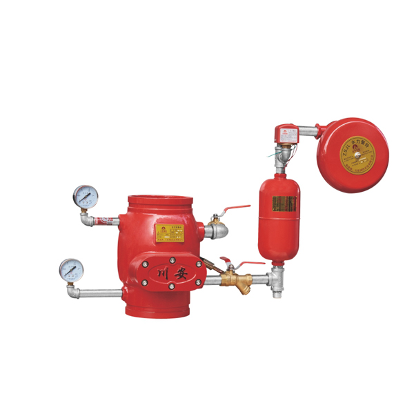
[IMAGE: grooved alarm valve ZSFZ(G) series DN100-DN250 Victaulic wet pipe sprinkler — CA-FIRE] [IMAGE ALT TEXT: grooved alarm valve ZSFZ grooved series DN100-DN250 fire sprinkler — CA-FIRE]
| Parameter | DN100 | DN150 | DN200 | DN250 |
|---|---|---|---|---|
| Model | ZSFZ 100(G) | ZSFZ 150(G) | ZSFZ 200(G) | ZSFZ 250(G) |
| Overall Height (mm) | 250 | 305 | 330 | 410 |
| Working Pressure | 1.6 MPa | 1.6 MPa | 1.6 MPa | 1.6 MPa |
| Seal Test Pressure | 3.2 MPa | 3.2 MPa | 3.2 MPa | 3.2 MPa |
| Strength Test Pressure | 6.4 MPa | 6.4 MPa | 6.4 MPa | 6.4 MPa |
| Hydraulic Resistance | < 0.02 MPa | < 0.02 MPa | < 0.02 MPa | < 0.02 MPa |
| Connection Method | Grooved — Victaulic IPS | Grooved — Victaulic IPS | Grooved — Victaulic IPS | Grooved — Victaulic IPS |
Key Parameters (All Models)
| Parameter | Specification |
|---|---|
| Body Material | Ductile iron QT450-10, epoxy coated |
| Sealing Material | Nitrile rubber (NBR) |
| Applicable Medium | Water, foam-water mixture |
| Temperature Range | 4–70 °C |
| Pressure Switch Output | DC 24V / 0.5A |
| Alarm Output | Water motor alarm gong + pressure switch |
| Standard | GB 5135.2-2019, NFPA 13 |
How the Grooved Alarm Valve Works
The ZSFZ(G) grooved alarm valve operates on the same hydraulic principle as the flanged wet alarm valve — the grooved connection is a change of end connection only, not of operating principle.
Standby: The grooved alarm valve clapper is held seated by balanced water pressure on both the supply side and system side. Both pressure gauges show equal standby pressure. The alarm port is closed and the water motor alarm gong is silent.
Activation: When a sprinkler head opens, downstream pressure drops. The pressure differential lifts the clapper, water flows through the valve into the distribution network, and simultaneously enters the alarm port. Water passing through the alarm port drives the water motor alarm gong — a mechanical alarm device that produces a loud audible signal with no electrical power — and pressurises the pressure switch to send an electrical signal to the fire alarm control panel.
Dual alarm output: The water motor alarm gong and pressure switch activate simultaneously, providing both on-site audible alarm for building occupants and remote electronic notification to the fire alarm control panel. The retard chamber in the alarm line absorbs brief supply pressure fluctuations, preventing spurious activations while ensuring genuine fire events are detected without delay.
Reset: After the event, close the supply isolation valve, drain the system, replace operated sprinkler heads, reset the clapper manually, then slowly reopen the supply valve to refill and repressurise. The grooved coupling connections allow the valve to be removed for inspection or replacement without cutting the pipeline — two coupling bolts per joint.
Key Features of the ZSFZ(G) Grooved Alarm Valve
Grooved Connections — Fast Installation, Easy Maintenance
The defining advantage of the grooved alarm valve over its flanged equivalent is the speed and simplicity of the mechanical coupling connection. Each grooved joint requires a coupling gasket, two-piece housing and two bolts — no gasket centering, no flange bolt patterns and no torque wrench sequences. A single installer can complete both grooved joints at the alarm valve station in the time it takes two people to break out the first flanged joint on a comparable flanged alarm valve. On large projects where alarm valve stations are installed at multiple risers and floor levels, the cumulative installation time saving across all stations is significant.
Maintenance access is equally simplified. Removing the grooved alarm valve for annual inspection or clapper replacement requires releasing two bolts per coupling — the valve slides out of the pipeline in under a minute, without draining the entire riser or cutting any pipe. This ease of removal is particularly valuable in occupied buildings where system downtime for maintenance must be minimised.
Water Motor Alarm Gong — Mechanical Alarm Without Electrical Power
The alarm port of the ZSFZ(G) grooved alarm valve drives a water motor alarm gong — a mechanically operated bell device that requires no electrical supply to produce its audible alarm output. Water flowing through the alarm port enters the water motor, spinning the impeller and striking the gong at sufficient volume to be heard throughout the floor or zone. This independence from the building’s electrical system means the alarm continues to function even if the fire event compromises the electrical installation — a critical reliability factor that purely electronic alarm systems cannot match.
The water motor alarm gong output is supplemented by the pressure switch electrical signal, providing the remote monitoring connection to the fire alarm control panel that modern building management systems require. The combination of mechanical and electronic alarm outputs from a single grooved alarm valve station provides both redundancy and immediate local notification.
Low Hydraulic Resistance — < 0.02 MPa
The ZSFZ(G) grooved alarm valve body profile produces less than 0.02 MPa hydraulic resistance across the fully open valve — the same low-resistance figure as CA-FIRE’s flanged wet alarm valve, and significantly lower than many competitor products. This matters in hydraulic system design: every MPa of pressure consumed by the alarm valve station reduces the residual pressure available at the most remote sprinkler heads. The ZSFZ(G)’s low resistance figure minimises the hydraulic budget consumed by the alarm valve, supporting more efficient system designs with greater margin at remote heads.
NBR Sealing — Long-Term Watertightness
The clapper facing and alarm port seals are manufactured from nitrile rubber (NBR), selected for its combination of water resistance, oil resistance, age stability and consistent elasticity under sustained system pressure across the 4–70 °C operating temperature range. NBR maintains its sealing properties throughout the grooved alarm valve’s design service life without the hardening or compression set that can develop in inferior elastomer specifications — ensuring leak-free clapper seating and alarm port closure throughout the standby periods between system activations.
Compatible with Foam-Water Systems
The ZSFZ(G) grooved alarm valve is rated for use with both clean water and foam-water mixture as the system medium, making it suitable for foam-water spray and foam-water sprinkler systems in addition to standard wet pipe sprinkler systems. This compatibility extends the application range of the grooved alarm valve to high-hazard occupancies — catering kitchens, vehicle storage areas, fuel handling rooms and industrial facilities — where foam-water systems are specified for enhanced suppression performance on Class B fire risks.
Grooved Alarm Valve vs. Flanged Wet Alarm Valve
| Grooved Alarm Valve ZSFZ(G) | Flanged Wet Alarm Valve ZSFZ | |
|---|---|---|
| Connection method | Mechanical coupling — 2 bolts per joint | Bolted flange — multiple bolts per joint |
| Installation speed | ✓ Fast — minutes per joint | Slower — alignment and torquing |
| Maintenance removal | ✓ 2 bolts — slides out | Multiple flange bolts per joint |
| Available sizes | DN100–DN250 | DN65–DN300 |
| Fully grooved system fit | ✓ Seamless | Requires transition fitting |
| Joint rigidity | Good | ✓ Superior |
| Alarm output | Water motor gong + pressure switch | Water motor gong + pressure switch |
| Performance | Identical | Identical |
| Hydraulic resistance | < 0.02 MPa | < 0.02 MPa |
Specify the grooved alarm valve when the sprinkler system uses grooved pipework throughout, when installation programme speed is a priority, or when ease of future valve removal for inspection and maintenance is important. Specify the flanged wet alarm valve when the system uses flanged pipework, when sizes above DN250 are required, or when flanged connections are the project standard.
Applications
High-Rise Residential and Commercial Buildings
High-rise buildings using grooved pipework throughout the sprinkler riser system benefit from a fully grooved alarm valve station that maintains connection consistency from water supply connection to the last sprinkler head. The compact body height of the ZSFZ(G) — 250 mm at DN100 through 410 mm at DN250 — fits comfortably in the confined riser cupboards and mechanical floors typical of high-rise construction, and the grooved connections allow installation in restricted access conditions where flanged bolt work would be impractical.
Fast-Track Construction Projects
On construction programmes where mechanical fit-out windows are compressed and labour efficiency is critical, the grooved alarm valve’s installation speed advantage compounds across every alarm valve station in the building. Projects with multiple riser zones — a typical high-rise commercial building may have ten or more alarm valve stations — realise meaningful schedule and cost savings from specifying grooved alarm valves throughout.
Retrofit and Refurbishment of Existing Grooved Systems
Replacing or upgrading alarm valve stations in existing buildings with grooved sprinkler pipework is straightforward with the ZSFZ(G) — the grooved connections match directly to the existing pipeline without any pipe modification, and the valve is dimensionally compatible with all standard Victaulic IPS grooved couplings. No hot work, no cutting and no flanged spool pieces are required for a clean retrofit installation.
Shopping Centres, Hotels and Institutional Buildings
Large commercial and institutional buildings using grooved sprinkler systems throughout install grooved alarm valves at each zone riser to maintain the fast-installation, easy-maintenance characteristics of the grooved system right through to the alarm valve station. Compatibility with foam-water mixture extends the ZSFZ(G)’s suitability to catering kitchens, vehicle parking areas and other foam-water protected zones within the same facility.
Industrial and Logistics Facilities
Warehouses, distribution centres and manufacturing facilities with large-area wet pipe or foam-water sprinkler systems using grooved pipework throughout specify the grooved alarm valve at each zone control station. The ease of removal for annual inspection is particularly valued in 24/7 operating facilities where system downtime for maintenance must be kept to an absolute minimum.
Installation Guidelines
Pre-Installation Checklist
- Confirm the grooved alarm valve nominal diameter and groove standard (IPS) match the pipeline pipe outside diameter and coupling specification.
- Check pipe groove dimensions at both inlet and outlet connections — groove width and depth must be within the coupling manufacturer’s tolerance.
- Confirm the installation location provides adequate clearance for alarm accessories, pressure gauges, test connection and maintenance access — minimum 600 mm on all sides recommended.
- Inspect the valve body, clapper and grooved faces for transit damage before installation.
Grooved Joint Assembly
Lubricate the mechanical coupling gaskets with the coupling manufacturer’s approved EPDM or NBR-compatible lubricant — do not use petroleum-based lubricants on rubber gaskets. Position the grooved alarm valve between the inlet and outlet pipe ends with the flow direction arrow aligned to the pipeline flow direction — supply below, system above. Fit the coupling housing halves over both grooved ends, insert the coupling bolts and tighten alternately in even sequence until the housing pads achieve firm metal-to-metal contact. Check both couplings for uniform gasket seating before pressurising.
Alarm Accessory Connection
Connect the retard chamber, water motor alarm gong and pressure switch to the alarm port using appropriate stainless steel or brass tubing and fittings. Mount the water motor alarm gong in an external or accessible location where its audible output will be heard throughout the protected zone. Connect the pressure switch electrical output to the fire alarm control panel in accordance with the system design and local electrical code requirements.
Commissioning
Fill the system from the supply side, purge air through the inspector’s test connection, and confirm both pressure gauges stabilise at equal standby pressure. Conduct a full-flow alarm test by opening the inspector’s test connection and verifying: clapper lifts under flow, water motor alarm gong activates, pressure switch sends signal to control panel, and both gauges show the correct pressure differential during flow. Record all commissioning test results.
Maintenance Schedule
Per NFPA 25 requirements:
| Frequency | Task |
|---|---|
| Weekly | Visual inspection — both pressure gauges, valve body, grooved coupling joints and alarm piping for leaks or damage |
| Monthly | Confirm upstream isolation valve is fully open and supervised |
| Quarterly | Water flow alarm test via inspector’s test connection — verify water motor alarm gong and pressure switch both activate; check retard chamber drain |
| Annually | Remove valve via grooved couplings for full internal inspection — check clapper, NBR seat facing, alarm port, retard chamber; inspect grooved coupling gaskets; check all connections |
| Every 5 years | Replace NBR clapper facing and grooved coupling gaskets as preventive maintenance |
Frequently Asked Questions
What is the difference between a grooved alarm valve and a flanged wet alarm valve?
The operating principle, alarm output and performance specifications are identical. The difference is the end connection method — grooved mechanical couplings versus bolted flanges. The grooved alarm valve installs faster, is easier to remove for maintenance and integrates seamlessly into fully grooved pipeline systems. The flanged wet alarm valve is available in a wider size range (DN65–DN300 vs DN100–DN250) and provides a more rigid joint. Selection depends on the pipeline connection standard and project priorities.
Is the grooved alarm valve compatible with all grooved coupling manufacturers?
The ZSFZ(G) grooved alarm valve is machined to Victaulic IPS grooved standard, compatible with Victaulic and all major IPS-standard grooved coupling manufacturers. Confirm the pipe outside diameter and groove standard with your coupling supplier before installation to ensure dimensional compatibility.
Does the water motor alarm gong require electrical power?
No. The water motor alarm gong is driven entirely by water flow through the alarm port — it produces its audible output mechanically without any electrical supply. This makes the grooved alarm valve’s local alarm function completely independent of the building’s electrical system, providing reliable alarm initiation even in fire events that compromise the electrical installation. The pressure switch in the alarm line requires electrical power only to send its signal to the fire alarm control panel.
Can the grooved alarm valve be used with foam-water systems?
Yes. The ZSFZ(G) grooved alarm valve is rated for both clean water and foam-water mixture, making it compatible with foam-water sprinkler and spray systems in addition to standard wet pipe systems.
What upstream isolation valve should be specified with the grooved alarm valve?
A supervised isolation valve must be installed immediately upstream of the grooved alarm valve per NFPA 25 requirements. CA-FIRE’s grooved signal gate valve is the directly compatible upstream isolation valve — grooved connections at both ends, matching the fully grooved system specification, with integrated tamper switch for supervisory monitoring. Alternatively, a grooved signal butterfly valve can be specified where space is constrained.
Get a Quote
Contact CA-FIRE for pricing, technical drawings, project specifications or OEM supply enquiries. Our engineering team responds within one business day.
- Email: sales@ca-fire.com
- Mobile: +86 13400715622 | WhatsApp: +86 18150362095
- WeChat: 404863577
- Website: www.ca-fire.com
Related products: Wet Alarm Valve — Flanged · Stainless Steel Alarm Valve · Dry Alarm Valve · Pre-Action Alarm Device · Grooved Signal Gate Valve · Alarm Check Valve Series
For wet alarm valve installation, testing and maintenance requirements, refer to NFPA 13 and NFPA 25.
| Specification Item | DN100 | DN150 | DN200 | DN250 |
|---|---|---|---|---|
| Model | ZSFZ 100(G) | ZSFZ 150(G) | ZSFZ 200(G) | ZSFZ 250(G) |
| Overall Height (mm) | 250 | 305 | 330 | 410 |
| Nominal Working Pressure | 1.6 MPa | 1.6 MPa | 1.6 MPa | 1.6 MPa |
| Seal Test Pressure | 3.2 MPa | 3.2 MPa | 3.2 MPa | 3.2 MPa |
| Strength Test Pressure | 6.4 MPa | 6.4 MPa | 6.4 MPa | 6.4 MPa |
| Hydraulic Resistance | < 0.02 MPa | < 0.02 MPa | < 0.02 MPa | < 0.02 MPa |
| Connection Method | Grooved clamping | Grooved clamping | Grooved clamping | Grooved clamping |
| Applicable Medium | Clean water; foam mixture liquid (all models) | |||
| Medium Temperature Range | 4 °C – 70 °C (all models) | |||
| Switch Contact Capacity | DC 24 V, 0.5 A (all models) | |||
| Sealing Material | Nitrile rubber (NBR) (all models) | |||
| Valve Body Material | Ductile iron QT450-10 (all models) | |||
| Surface Treatment | Epoxy powder anti-corrosion coating (all models) |