Foam Fire Hydrant — Chemical Plant, Refinery & Hangar Series | CA-FIRE
✓ GB Standard — Foam Hydrant✓ DN100 / DN150 · 1.6 MPa✓ Water + Foam Mixed Supply✓ AFFF · AR-AFFF Compatible✓ Anti-Impact Breakaway✓ Auto-Drain · Self-Sealing✓ ISO 9001 · GB · CE
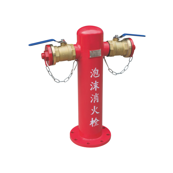
The CA-FIRE foam fire hydrant series is purpose-built for high-hazard industrial sites where water alone is insufficient for fire control — petroleum refineries, chemical plants, oil storage tank farms, LNG terminals, aviation fuel facilities and aircraft hangars. Unlike a standard water hydrant, the foam hydrant’s internal wetted components are specifically engineered for continuous contact with AFFF and AR-AFFF foam concentrate, and its outlet configuration delivers pre-mixed foam solution directly from the supply main to the hose coupling without requiring a separate proportioner at the hydrant point. The series covers three structural variants — Standard (SSP), Anti-Impact (SSPF), and Anti-Impact + Pressure-Regulating (SSPFT) — in DN100 and DN150 inlet sizes at 1.6 MPa working pressure. All models incorporate auto-drain, are compatible with 3% and 6% AFFF and AR-AFFF foam concentrates, and can be manufactured in frost-protected variants for cold climate installations.
Why a Dedicated Foam Hydrant — Not a Standard Water Hydrant
|
The Problem with Standard Hydrants on Foam Systems A standard GB water hydrant (SS series) is manufactured with materials optimised for continuous water contact — standard EPDM seals, uncoated ductile iron wetted surfaces, and standard-thread outlet ports. When these hydrants are connected to a foam supply main carrying 3%–6% AFFF or AR-AFFF pre-mixed solution, three problems arise over time. First, foam concentrate is chemically more aggressive than water toward standard elastomers — EPDM seals degrade faster, leading to seepage and loss of foam concentrate from the supply main. Second, foam residue accumulates inside the hydrant body between deployments, degrading foam concentrate quality and potentially blocking the drain valve. Third, standard outlet coatings are not rated for the long-term chemical exposure from foam concentrate, leading to accelerated internal corrosion. For fire protection authorities inspecting petroleum and chemical facilities, using a standard water hydrant on a foam supply main is a non-compliance finding — GB 50151 (泡沫灭火系统技术规范) requires purpose-built foam-rated components throughout the foam supply network. |
What the SSP Foam Hydrant Provides CA-FIRE’s SSP foam hydrant series addresses all three issues. The internal wetted materials are upgraded for foam service: fluorine-rubber (FKM) or foam-rated EPDM seals resistant to long-term AFFF and AR-AFFF exposure; epoxy-coated internal surfaces on the body and valve chamber to prevent foam concentrate-induced corrosion; and enhanced drain valve design that fully expels foam residue after each use rather than leaving pooled concentrate inside the body. The outlet configuration provides both a water takeoff port (for cooling water) and a foam solution hose coupling (for suppression) from the same hydrant — a single connection point serves the two critical fire response needs at a petroleum or chemical site: simultaneous water cooling of exposed structures and foam application to the burning liquid surface. This dual-function capability reduces the number of hydrant points required on a tank farm perimeter road, simplifies the supply main layout, and speeds up fire brigade deployment — one standpipe gives access to both suppression and cooling simultaneously. |
Three Variants — Select by Site Hazard Profile
|
Standard Foam Type — SSP 普通泡沫系列 The baseline foam hydrant for chemical plant and refinery perimeter roads, storage tank bund areas and foam system infrastructure where vehicle collision risk is low. Foam-rated internal materials throughout; auto-drain after each use; dual water + foam outlet configuration. Suitable for pedestrian-only perimeter paths, pump house surrounds and locations where heavy vehicle access is controlled and segregated from the hydrant zone.
|
Anti-Impact Foam Type — SSPF 泡沫防撞系列 Combines the SSP foam-rated construction with the breakaway collar anti-impact mechanism from the SS-D series. On vehicle impact, the upper body detaches at the designed-fracture collar — the main valve and supply connection remain sealed, preventing loss of pressurised foam solution and avoiding the catastrophic flooding scenario that would occur if a tank farm supply main were opened by a sheared hydrant. Specify for tank farm perimeter roads used by tanker vehicles, road tankers and fuel delivery trucks, refinery internal roads, and any location where mobile plant operates in the vicinity of hydrant positions.
|
Anti-Impact + Pressure-Regulating — SSPFT 泡沫防撞调压系列 The most fully specified variant — combines foam-rated materials, anti-impact breakaway collar, and an integrated pressure-reducing valve in a single unit. Specify for sites where the foam supply main operates at elevated pressure above the safe hose-handling range, combined with vehicle traffic risk. High-pressure foam supply mains are common in large refineries and petrochemical complexes where the foam pump system is designed to maintain pressure across an extensive supply ring main — supply pressure at hydrant points frequently exceeds 0.8–1.0 MPa. The SSPFT delivers regulated outlet pressure safe for fire crew hose operations without a separate PRV assembly.
|
Technical Specifications — Full Model Range
| Series | Model | Pressure | Inlet | Inlet DN | Water Takeoff | Hose Coupling | Opening Height |
|---|---|---|---|---|---|---|---|
| Standard Foam 普通泡沫 SSP |
SSP100/65-1.6 | 1.6 MPa | Flange | DN100 | M125×6 | 2-KWS65 | ≥50 |
| SSP150/65-1.6 | DN150 | M170×6 | 2-KWS65 | ≥55 | |||
| SSP150/80-1.6 | DN150 | M170×6 | 2-KWS80 | ≥55 | |||
| Anti-Impact Foam 泡沫防撞 SSPF |
SSPF100/65-1.6 | DN100 | M125×6 | 2-KWS65 | ≥50 | ||
| SSPF150/65-1.6 | DN150 | M170×6 | 2-KWS65 | ≥55 | |||
| SSPF150/80-1.6 | DN150 | M170×6 | 2-KWS80 | ≥55 | |||
| Anti-Impact + PRV 泡沫防撞调压 SSPFT |
SSPFT100/65-1.6 | DN100 | M125×6 | 2-KWS65 | — | ||
| SSPFT150/65-1.6 | DN150 | M170×6 | 2-KWS65 | — | |||
| SSPFT150/80-1.6 | DN150 | M170×6 | 2-KWS80 | — |
Common Parameters — All Models
| Parameter | Specification |
|---|---|
| Compliance Standard | GB 4452 · GB 50151 (泡沫灭火系统) · ISO 9001:2015 · CE |
| Rated Working Pressure | 1.6 MPa |
| Test Pressure | 2.4 MPa — 30-minute hydrostatic hold, zero leakage |
| Inlet Connection | Flange — GB standard flange dimensions |
| DN100 Outlets | Water takeoff M125×6 + foam hose coupling 2-KWS65 |
| DN150 Outlets (65 models) | Water takeoff M170×6 + foam hose coupling 2-KWS65 |
| DN150 Outlets (80 models) | Water takeoff M170×6 + foam hose coupling 2-KWS80 |
| Body Material | Ductile iron — epoxy-coated internal wetted surfaces |
| Seals | FKM (fluorine rubber) / foam-rated EPDM — resistant to AFFF & AR-AFFF long-term exposure |
| Foam Compatibility | AFFF 3% & 6% · AR-AFFF 3% & 6% · Water · Foam-water mixed supply |
| Auto-Drain | Built-in — expels foam concentrate residue after each use · Frost-protected variant available |
| Surface Treatment | Electrostatic powder coating RAL 3000 red — enhanced corrosion resistance for chemical plant environments |
| Special Options | Encrypted (加密型) · Frost-protected · Custom inlet/outlet configuration per user requirement |
| Warranty | 2 years |
* Frost-protected variants with air-vent drain system available on all models for cold climate installations. Custom inlet/outlet configurations and non-standard flange dimensions available on request.
Key Technical Features
|
🧪 Foam-Rated Internal Materials — FKM Seals + Epoxy Body The fundamental distinction between the SSP foam hydrant and a standard SS water hydrant is the upgrade of all internal wetted components to foam-service specification. Fluorine rubber (FKM) valve seals replace standard EPDM, providing resistance to AFFF and AR-AFFF concentrates over the system’s service life without swelling, cracking or compression set. Standard EPDM degrades in extended foam contact and is not acceptable under GB 50151 for foam system components. Epoxy coating on all internal wetted metal surfaces prevents the electrochemical corrosion that foam concentrate accelerates on bare ductile iron — particularly in the valve chamber and the drain sump where concentrate residue pools between deployments. This coating is applied to a minimum dry film thickness of 250 μm and tested for adhesion, impact resistance and chemical resistance to the specified foam concentrate types. FKM Seals · Epoxy 250μm DFT · AFFF + AR-AFFF Rated · GB 50151 |
💥 Anti-Impact Breakaway — SSPF / SSPFT Series On petroleum and chemical sites, vehicle impact on a hydrant carries a risk far more serious than on a standard municipal site — a sheared hydrant on a pressurised foam supply main would release foam concentrate under pressure, creating a slip hazard across the road surface and potentially triggering a foam system pressure alarm that activates other system components incorrectly. The SSPF/SSPFT breakaway collar fractures at a designed shear load, releasing the upper body while the main valve remains closed and sealed. The foam supply main retains full pressure; no foam is released; and the system can be returned to full service by replacing only the upper body section — no excavation, no mainline repair, no foam concentrate loss. This mechanism is aligned with the requirements of NFPA 11 (Standard for Low-, Medium-, and High-Expansion Foam) guidance on foam system component protection on vehicle-accessible perimeter roads. Breakaway Collar · Valve Stays Closed · No Foam Loss on Impact |
|
🚿 Dual Outlet — Water Cooling + Foam Suppression from One Point Every SSP series foam hydrant provides two separate outlets from a single connection point: a water takeoff port (M125×6 for DN100 / M170×6 for DN150) for connecting a water hose for cooling of exposed process equipment, pipework and structural steel, and a foam solution hose coupling (2-KWS65 or 2-KWS80) for connecting a foam delivery hose for direct foam application to the fire surface. At a petroleum fire scenario, the fire brigade simultaneously needs cooling water on adjacent tanks and structures, and foam on the burning liquid surface. The SSP dual-outlet design allows both operations from a single standpipe without a Y-splitter or secondary hydrant connection — reducing deployment time and the number of hydrant points required along the tank farm perimeter. Water Cooling + Foam Suppression · Single Connection Point · Fast Deployment |
⚖️ Integrated PRV — SSPFT Series Large refinery and petrochemical foam ring mains are designed to maintain a minimum residual pressure at the most remote hydrant under full design flow — this requires supply pressures significantly above the safe hose-handling limit at hydrant positions closer to the foam pump station. Supply pressures of 0.8–1.2 MPa at near-pump hydrant points are common in large facilities. The SSPFT’s integrated pressure-reducing valve limits outlet pressure to the factory-set safe value without requiring a separate foam-rated PRV assembly. The PRV mechanism is manufactured from materials compatible with foam concentrate — standard PRV assemblies often use non-foam-rated internals and degrade rapidly in foam service. Factory-set pressure can be adjusted on-site within the rated range by a competent engineer without removing the hydrant from service. Foam-Rated PRV · Integrated · Field-Adjustable · No Separate Assembly |
Model Selection Guide
| Your Site / Requirement | Recommended | Reason |
|---|---|---|
| Chemical plant or small refinery — perimeter footpaths, pump house surrounds, low vehicle risk | SSP100/65-1.6 | Foam-rated construction, dual water + foam outlets, lowest cost in the series. Sufficient where vehicle collision is not a realistic risk. |
| Oil storage tank farm perimeter road, refinery internal road — tankers, road vehicles and mobile plant operate in the area | SSPF100/65-1.6 or SSPF150/65-1.6 | Anti-impact breakaway prevents foam supply main pressurisation and foam loss on vehicle collision. DN150 if fire engineering requires higher flow. |
| Large refinery, petrochemical complex or LNG terminal — high-pressure foam ring main, vehicle traffic risk on perimeter roads | SSPFT150/80-1.6 | Fully specified variant: DN150 large flow + anti-impact breakaway + integrated foam-rated PRV. Covers all hazard scenarios at major petroleum facilities. |
| Aircraft hangar, military airfield or civil aviation fuel facility | SSPF100/65-1.6 or SSPFT100/65-1.6 | Aircraft hangars require AR-AFFF compatible foam systems (aqueous film-forming foam with AR resistance for aviation fuel). Anti-impact specified for vehicle apron areas; SSPFT for high-pressure ramp hydrant positions. |
| Any foam hydrant position in a northern China or cold climate location | Any SSP/SSPF/SSPFT model — frost-protected variant | Frost-protected air-vent drain system prevents barrel freeze. Confirm installation location and design frost depth at enquiry — CA-FIRE specifies the correct barrel length for the project site. |
| Maximum flow rate from foam hydrant — DN150 supply main available, large fire scenario design basis | SSP150/80-1.6, SSPF150/80-1.6 or SSPFT150/80-1.6 | DN150 inlet with KWS80 foam outlet provides highest flow capacity — specify the structural variant (SSP/SSPF/SSPFT) based on vehicle risk and pressure management requirement. |
How the Foam Fire Hydrant Works at a Petroleum Fire
The SSP foam fire hydrant operates identically to a standard above-ground hydrant in terms of mechanical operation — the difference is in what flows through it and how the outlets are used. At a petroleum or chemical plant fire, two simultaneous operations are typically required: foam application to the burning liquid surface, and water cooling of adjacent exposed tanks, vessels and structures.
|
1
Foam Supply System Activated When a fire is declared at the facility, the foam pump station starts (automatically or manually) and pressurises the foam supply ring main with pre-mixed foam solution from the foam bladder tank or inline proportioner. The SSP foam hydrant is already connected to this pressurised ring main through its flange inlet — ready for immediate deployment as soon as the valve is opened. |
2
Fire Crew Opens the Main Valve The fire crew uses the operating wrench on the pentagonal top nut to open the main valve. Pre-mixed foam solution flows from the ring main through the hydrant body and is available at both outlet ports simultaneously. For SSPFT models, the integrated PRV automatically limits outlet pressure to the safe operating value as flow begins — no adjustment required by the crew. |
|
3
Dual-Purpose Deployment One crew member connects a foam delivery hose to the KWS foam coupling outlet and directs foam solution at the burning liquid surface through a foam branch pipe or foam monitor. A second crew member connects a cooling water hose to the M-thread water takeoff port and directs water spray at adjacent exposed tanks or structural steel. Both operations run simultaneously from the single hydrant point without a splitter. |
4
Shutdown & Auto-Drain Close the main valve. Disconnect hose lines. Replace outlet caps. The auto-drain valve opens as the main valve closes, expelling residual foam solution from the barrel into the drain zone below ground. This prevents foam concentrate from pooling inside the hydrant body between deployments and degrading the epoxy coating or seal materials over time. After extended foam system operation, flush the supply ring main per GB 50151 maintenance requirements to remove residual concentrate. |
Installation — Foam System Integration
Connection to Foam Supply Main
The SSP foam hydrant connects to the foam supply ring main via its GB flange inlet in the same manner as a standard water hydrant connects to a water main. However, the supply main must be a foam-rated pipeline — internal surface coating or lining compatible with the specified foam concentrate type, and all associated valves, fittings and components must meet GB 50151 foam system component requirements. Confirm with the foam system designer that the supply main specification is compatible with the hydrant inlet connection before finalising the installation design.
Site Position Requirements
Per GB 50151 and GB 50160 (石油化工企业设计防火规范): foam hydrants on tank farm perimeter roads should be positioned outside the bund wall, accessible to fire vehicles without entering the bunded area; minimum 5 m from the nearest tank shell to avoid heat damage during a tank fire event; spacing per the facility fire protection design — typically 30–60 m intervals around tank farm perimeters. For SSPF/SSPFT anti-impact models, the hydrant should be positioned so that the breakaway plane is aligned perpendicular to the predominant vehicle traffic direction — maximising the probability that a vehicle impact acts in the correct shear direction for the collar to fracture as designed.
Installation Steps
Set the hydrant on the prepared concrete plinth and verify verticality. Fit foam-rated flange gasket (FKM or PTFE-encapsulated — not standard EPDM) between the hydrant inlet flange and the foam supply main tee. Tighten flange bolts in a cross pattern to 45–55 N·m. Secure to plinth with chemical anchor bolts. Conduct commissioning hydrostatic test at 2.4 MPa with water first — do not use foam concentrate during pressure testing to avoid contaminating the drainage zone. After satisfactory water pressure test, flush the system through the hydrant outlets to confirm clear flow before connecting to the live foam supply main. For SSPFT models, verify PRV outlet pressure with a calibrated gauge at the rated flow condition before final commissioning sign-off.
Anti-Impact (SSPF/SSPFT) Collar Assembly
The breakaway collar must be torqued to the specified value — do not over-tighten, weld or apply sealant to the collar joint as this defeats the designed fracture function. After any vehicle impact event: isolate the upstream section valve; confirm main valve is closed and no foam is escaping; remove the fractured upper body; inspect the lower valve body for damage to the valve seat, stem gland and body casting; fit a factory-supplied replacement upper body; re-torque collar to specification; pressure test before returning to service. Always inspect the foam supply main upstream isolation valve to confirm it operates freely after an impact event — vehicle collisions that shear a hydrant may also transmit shock loads along the supply main.
Maintenance Schedule
| Frequency | Task |
|---|---|
| Monthly | Visual inspection of body, outlet caps and surface coating. Check for foam concentrate seepage at the outlet caps, valve gland or flange joint — any weeping indicates seal degradation and requires immediate investigation. Verify outlet caps are correctly seated. Inspect surrounding ground surface for foam residue indicating drain valve leakage into the plinth area. For SSPF/SSPFT: inspect the breakaway collar for cracks, deformation or unreported impact damage. |
| Quarterly | Operational test: open the main valve with no hose connected and confirm free flow from both outlets; close and confirm auto-drain operates within 5 minutes. Remove outlet caps and inspect FKM coupling seals — replace with foam-rated genuine CA-FIRE parts if degraded. Apply Molykote or PTFE-based grease to the operating spindle (do not use petroleum-based grease, which may contaminate the foam solution). For SSPFT: check PRV outlet pressure with a calibrated gauge at low flow — compare against the commissioning record and investigate any deviation > 0.05 MPa. |
| Annual | Full hydrostatic test at 2.4 MPa (30 minutes, zero leakage). Inspect internal epoxy coating for blistering, peeling or chemical attack — recoat or replace body sections as required. Inspect and clean the drain valve port. For SSPFT: full PRV calibration check at rated flow condition. Update facility fire protection maintenance records per GB 50151 requirements. Foam system periodic testing per facility emergency response plan — coordinate foam hydrant inspection with the annual system flow test. |
Applications
|
Petroleum Refineries & Tank Farms Crude oil and refined product storage tank farms, refinery process unit perimeters, loading rack areas and marine jetty berths. The foam hydrant serves as the primary fire brigade access point for both foam application to tank fires and water cooling of adjacent tanks under heat exposure. Anti-impact SSPF specified for all road-accessible positions. → SSPF150/65-1.6 or SSPFT150/80-1.6 |
Chemical Plants & Petrochemical Complexes Ethylene crackers, aromatics plants, solvent storage, specialty chemical production facilities and integrated petrochemical complexes. Class B flammable liquid fire risk requires AR-AFFF compatible foam systems throughout — the SSP foam hydrant’s FKM seals and epoxy coating are rated for the full range of polar and non-polar solvent foam concentrates specified at these facilities. → SSPF100/65-1.6 (standard sites) · SSPFT (high-pressure mains) |
LNG & LPG Terminals Liquefied natural gas receiving terminals, LPG storage and distribution facilities, gas processing plants and cryogenic storage installations. Foam hydrants on these facilities serve the Class B fire scenarios at loading arms and product transfer areas. Stainless steel internal components available on request for installations where cryogenic spill risk may expose the hydrant body to extreme temperature gradients. → SSPF150/80-1.6 with foam-rated PRV |
|
Aircraft Hangars & Airfield Fuel Facilities Commercial aircraft maintenance hangars, military aviation facilities, airfield fuel storage and hydrant refuelling systems. Aviation jet fuel fires require AR-AFFF (alcohol-resistant AFFF) at 3% application rate. The SSP foam hydrant is rated for AR-AFFF service throughout. Specify anti-impact variant for all positions on aircraft movement aprons or vehicle access routes. → SSPF100/65-1.6 (AR-AFFF rated) |
Paint & Solvent Production Facilities Paint manufacturing plants, coating raw material storage, adhesive production and solvent drum storage warehouses. Class B flammable liquid content requires foam suppression capability at perimeter hydrant positions. Standard SSP is appropriate for low vehicle-risk areas; SSPF for loading dock and drum handling areas. → SSP100/65-1.6 or SSPF100/65-1.6 |
Export — Industrial Projects with Foam System Requirements International refinery, petrochemical and terminal projects where Chinese EPC contractors specify GB standard foam fire protection equipment, or where the project authority accepts GB 50151 as the applicable design standard alongside NFPA 11 or EN 13565. CA-FIRE supplies the full SSP foam hydrant series to industrial EPC projects across 30+ countries. → Per project fire engineer’s specification |
Frequently Asked Questions
What is the difference between a foam fire hydrant and a standard water fire hydrant?
A standard water hydrant (SS series) is designed for water supply only — its internal materials are optimised for continuous water contact. A foam fire hydrant (SSP series) has three additional features: (1) foam-rated internal materials — FKM seals and epoxy-coated wetted surfaces that resist long-term AFFF and AR-AFFF exposure without degradation, as required by GB 50151; (2) dual outlet configuration — a water takeoff port and a foam solution hose coupling from the same hydrant body, allowing simultaneous water cooling and foam suppression from a single connection; and (3) enhanced drain design that fully expels foam concentrate residue after each use. Using a standard water hydrant on a foam supply main is a GB 50151 non-compliance finding — always specify the foam hydrant series for foam system connections.
Is the foam hydrant compatible with AR-AFFF as well as standard AFFF?
Yes — all SSP series foam hydrants are compatible with both standard AFFF (aqueous film-forming foam) and AR-AFFF (alcohol-resistant AFFF) at 3% and 6% concentration ratios. AR-AFFF is required for polar solvent fires (alcohols, ketones, esters) and for aviation fuel facilities per ICAO/CAA requirements. The FKM seals and epoxy coating used in the SSP series are tested against the chemical attack profile of both concentrate types. Confirm the specific foam concentrate brand and concentration at enquiry — CA-FIRE can provide chemical compatibility documentation for the relevant concentrate.
Does the foam hydrant include the foam proportioner, or does it just deliver pre-mixed solution?
The SSP foam hydrant is a delivery point — it does not contain a proportioner. It receives pre-mixed foam solution from the foam supply main (which is connected to a separate foam proportioning system — typically a pressure proportioning foam bladder tank system or a pump-and-proportioner assembly) and delivers this pre-mixed solution to the hose outlet. The proportioning ratio (3% or 6%) is set at the proportioning system, not at the hydrant. This is the correct design for fixed foam ring main systems per GB 50151. If a portable proportioner at the hydrant point is required, specify a separate inline inductor device — CA-FIRE can advise on the correct configuration for the project design basis.
What GB and international standards apply to foam fire hydrants in China?
The primary Chinese standards are GB 4452 (outdoor fire hydrants — product standard) and GB 50151 (泡沫灭火系统技术规范 — Foam Fire Extinguishing System Technical Code). GB 50151 governs foam system design, component selection, installation and commissioning, and requires that all wetted components in the foam supply system — including hydrants — are rated for the specified foam concentrate type. The facility design standard for petroleum and chemical plants is GB 50160 (石油化工企业设计防火规范) and GB 50183 (石油天然气工程设计防火规范) for oil and gas. For international projects, NFPA 11 (Low-, Medium-, and High-Expansion Foam standard) is the most widely referenced international foam system standard and is compatible in principle with the CA-FIRE SSP series design.
Can the foam hydrant also deliver plain water for cooling, or foam only?
All SSP foam hydrants deliver whatever medium is supplied from the connected supply main. If the hydrant is connected to a foam supply ring main carrying pre-mixed foam solution, both the water takeoff port and the foam outlet deliver foam solution — both outlets carry the same fluid. The “water takeoff” designation refers to the outlet’s mechanical configuration (M-thread for direct hose or monitor connection), not the medium. If the facility design requires the water cooling and foam suppression outlets to carry different media (pure water vs foam solution), this requires separate supply mains connecting to each outlet — confirm the system design with the facility fire engineer before specifying. CA-FIRE’s engineering team is available to advise on optimal system configuration.
Applicable Standards & References
| Standard | Scope |
|---|---|
| GB 4452 | 室外消火栓 — Outdoor Fire Hydrants. Primary product standard for all GB outdoor hydrants including the SSP foam series. Specifies performance, dimensions, materials, testing and marking. |
| GB 50151 | 泡沫灭火系统技术规范 — Technical Code for Foam Fire Extinguishing Systems. Governs foam system design, component selection (including hydrant material ratings), installation, commissioning and maintenance. Requires foam-rated components throughout the foam supply network — the primary reason a dedicated foam hydrant is specified rather than a standard water hydrant. |
| GB 50160 / GB 50183 | 石油化工企业设计防火规范 / 石油天然气工程设计防火规范 — Fire safety design codes for petrochemical plants and oil and gas facilities. Govern foam hydrant spacing, system design requirements and location criteria on petroleum and gas sites. |
| NFPA 11 | Standard for Low-, Medium-, and High-Expansion Foam. The primary international reference standard for foam fire suppression systems. Referenced on international petroleum and aviation projects alongside GB 50151. NFPA 11 guidance on foam system component protection and anti-impact requirements for vehicle-accessible perimeter hydrant positions is reflected in the SSPF/SSPFT breakaway collar design. |
| ISO 9001:2015 | CA-FIRE quality management system certification — covers design, manufacturing, testing and supply chain for all SSP foam fire hydrant products. |
Related Products
|
Foam Supply System Foam Bladder Tank — Pressure Proportioning System The upstream foam supply source for the SSP foam hydrant ring main. Bladder tank proportioning systems deliver pre-mixed AFFF/AR-AFFF solution at 3% or 6% into the foam supply main — feeding the foam hydrant without a pump or power supply. |
GB Standard Water Hydrant Above-Ground Fire Hydrant — Standard, Anti-Impact & Large-Flow Water-only GB SS series pillar hydrant for water supply zones on the same facility where foam hydrants cover the Class B hazard areas. Standard (SS-H), Anti-Impact (SS-D) and Large-Flow (SS-A) variants. |
All Types · Full Range Fire Hydrant — Category Overview Compare all CA-FIRE fire hydrant types — foam, GB above-ground, underground, Russian standard, French type and BS750 — with specification table and application selection guide. |
Get a Quote — Foam Fire Hydrant
GB 4452 · GB 50151 · DN100 / DN150 · 1.6 MPa · AFFF & AR-AFFF Compatible
Standard (SSP) · Anti-Impact (SSPF) · Anti-Impact + PRV (SSPFT) · Factory Direct
sales@ca-fire.com
WhatsApp: +86 18150362095
+86 13400715622
WeChat: 404863577