
Grooved Butterfly Valve for Fire Protection — Victaulic Compatible DN50–DN300
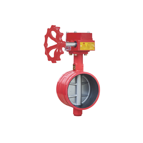
The CA-FIRE grooved butterfly valve (ZSDF8 / ZSXDF8 series) is a Victaulic-compatible grooved end butterfly valve designed for fire sprinkler systems, standpipe systems, and foam suppression pipelines using grooved mechanical pipe couplings. Available in four variants covering gear operated and lever operated, with or without tamper switch — all in DN50 through DN300 (gear) and DN50 through DN150 (lever), rated at 1.6 MPa working pressure.
The grooved butterfly valve installs using standard grooved pipe couplings (Victaulic style, ISO 6182-12 compliant) instead of bolted flanges. This eliminates flange drilling and bolt-circle alignment, reducing installation labor by up to 40% on large fire main projects. The grooved connection also allows angular pipe deflection, making the grooved butterfly valve the preferred isolation valve for modular fire suppression systems, offshore platform fire mains, and any system where pipe thermal movement or vibration isolation is required.
This page covers grooved end butterfly valves (ZSDF8 / ZSXDF8). For wafer type butterfly valves installed between flanges, see the Gear Operated Butterfly Valve and Lever Butterfly Valve pages. For hazardous area Ex-certified grooved valves, see the Explosion Proof Butterfly Valve page.
Key Features of the ZSDF8 / ZSXDF8 Grooved Butterfly Valve
- Victaulic-compatible grooved ends— conforms to Victaulic standard groove dimensions and ISO 6182-12 / AWWA C606 groove profiles. Compatible with all major grooved coupling brands including Victaulic, Gruvlok, and Anvil.
- Four model variants in one family:ZSXDF8 (gear + signal), ZSDF8 (gear, no signal), ZSXDF8-S (lever + signal), ZSDF8-S (lever, no signal) — same grooved body, different actuator and supervision method.
- ZSXDF8 and ZSXDF8-S tamper switchoutputs DC24V open/closed supervisory signal directly to the fire alarm control panel (FACP), satisfying NFPA 72 Chapter 17 and GB 50116 electrical supervision requirements.
- Faster installation than flanged valves— grooved couplings require no flange drilling, gasket alignment, or bolt torquing. A single technician can install a DN150 grooved butterfly valve in under 10 minutes using standard hand tools.
- Angular deflection capability— grooved couplings allow 1–3° of angular pipe deflection depending on pipe size, accommodating building settlement, thermal expansion, and vibration without rigid pipe stress.
- Worm gear (DN50–DN300) or lever (DN50–DN150) actuator— same grooved valve body, different actuator top-works. Gear operated for large DN or high-torque applications; lever for small DN branch isolations requiring fast quarter-turn operation.
- Cast iron GGG40 or stainless steel SS316 body— SS316 specified for offshore, coastal, foam concentrate, and seawater service. GGG40 for standard onshore fire water applications.
- EPDM resilient seat— rated for water, AFFF, AR-AFFF, and protein foam concentrate service at 4–80°C. Bi-directional sealing — either end can be upstream.
- Compliant with GB 5135.13 / GB 5135.2and tested to 6.4 MPa strength test pressure. Factory hydrostatic test certificate supplied with each valve.
Technical Specifications — All Four ZSDF8 / ZSXDF8 Models
The table below covers all four grooved butterfly valve models. Gear operated models (ZSDF8 / ZSXDF8) are available in DN50–DN300; lever operated models (ZSDF8-S / ZSXDF8-S) in DN50–DN150.
| Parameter | ZSXDF8 Gear+Signal | ZSDF8 Gear | ZSXDF8-S Lever+Signal | ZSDF8-S Lever |
| Model Number | ZSXDF8-Q-50-300-16 | ZSDF8-Q-50-300-16 | ZSXDF8-S-Q-50-150-16 | ZSDF8-S-Q-50-150-16 |
| Nominal Diameter | DN50–DN300 | DN50–DN300 | DN50–DN150 | DN50–DN150 |
| Working Pressure | 1.6 MPa | 1.6 MPa | 1.6 MPa | 1.6 MPa |
| Strength Test | 6.4 MPa | 6.4 MPa | 6.4 MPa | 6.4 MPa |
| Seal Test | 3.2 MPa | 3.2 MPa | 3.2 MPa | 3.2 MPa |
| Media | Water, foam-water | Water, foam-water | Water, foam-water | Water, foam-water |
| Actuator | Worm gear (涡轮) | Worm gear (涡轮) | Lever (手柄) | Lever (手柄) |
| Tamper Switch | DC24V 0.5A | None | DC24V 0.5A | None |
| Connection | Grooved (Victaulic) | Grooved (Victaulic) | Grooved (Victaulic) | Grooved (Victaulic) |
| Body Material | GGG40 / SS316 | GGG40 / SS316 | GGG40 / SS316 | GGG40 / SS316 |
| Temp. Range | 0–80°C | 4–70°C | 0–80°C | 4–70°C |
| GB Standard | GB 5135.13 | GB 5135.2 | GB 5135.13 | GB 5135.2 |
Structural Dimensions — Grooved End Face-to-Face Length
The grooved butterfly valve face-to-face dimension is longer than the equivalent wafer type because the grooved pipe ends must protrude beyond the valve body for coupling engagement. Grooved pipe end preparation (roll grooving or cut grooving) must conform to Victaulic standard or ISO 6182-12 groove dimensions. For wafer face-to-face dimensions, see the Gear Operated Butterfly Valve page.
| DN (mm) | 50 | 65 | 80 | 100 | 125 | 150 | 200 | 250 | 300 |
| Face-to-Face (mm) | 80 | 80 | 80 | 95 | 102 | 110 | 120 | 160 | 165 |
How the Grooved Butterfly Valve Installs and Operates
The ZSDF8 / ZSXDF8 grooved butterfly valve is installed using standard grooved mechanical pipe couplings. Here is the complete installation and operating sequence:
- Pipe end preparation: Both pipe ends connecting to the grooved butterfly valve must be roll-grooved or cut-grooved to the correct groove profile for the pipe size. Groove dimensions must comply with Victaulic standard, AWWA C606, or ISO 6182-12. The grooved butterfly valve body itself has factory-machined groove seats — no field preparation required on the valve.
- Coupling installation: Slide the grooved coupling housing halves over both pipe ends, with the coupling gasket centered over the pipe-to-valve gap. Align the coupling keys with the pipe grooves and tighten the bolts evenly. A flexible coupling allows angular deflection; a rigid coupling prevents movement — specify according to the system design requirement.
- Valve operation — gear type (ZSDF8 / ZSXDF8): The worm gear handwheel requires 15–30 full turns to move the disc 90° from open to closed. The gear mechanism provides 15:1 to 30:1 mechanical advantage — suitable for DN100–DN300 where direct lever torque would be excessive at 1.6 MPa working pressure.
- Valve operation — lever type (ZSDF8-S / ZSXDF8-S): The lever handle rotates 90° in a single motion from open to closed. Detent notches lock the lever at full-open and full-closed positions. Suitable for DN50–DN150 where direct quarter-turn lever torque is manageable.
- Tamper switch operation (ZSXDF8 / ZSXDF8-S only): The supervisory switch monitors valve disc position via a stem-mounted cam. In the fully open position, it outputs a continuous ‘OPEN’ signal (DC24V) to the FACP. Movement from full-open triggers a ‘TAMPER’ supervisory alarm within 1–2 actuator movements, per NFPA 72Chapter 17.
- System maintenance: Grooved couplings allow the butterfly valve to be removed from the pipeline without cutting pipe — simply loosen and remove both coupling housings. This reduces maintenance downtime significantly compared to flanged valves that require flange bolt removal and potential pipe disturbance.
Applications
The grooved butterfly valve is specified wherever the fire suppression system uses grooved pipe or where installation speed and flexibility are priorities:
- Fire sprinkler main risers and cross-mains— DN100–DN300 isolation valves on grooved steel pipe fire mains in commercial buildings, warehouses, and industrial facilities. The ZSXDF8 tamper switch version provides mandatory supervisory monitoring per NFPA 13 Section 8.16.
- Offshore oil and gas platform fire mains— topside fire water ring main isolation with SS316 body and IP54 tamper switch. Grooved couplings are preferred offshore because they allow angular pipe deflection to accommodate platform structural movement and eliminate the hot work associated with flange bolt torquing in Ex zones.
- Modular fire suppression skids— factory-assembled foam suppression and water mist skids where all piping is grooved for fast site installation and future module replacement. The grooved butterfly valve is the standard isolation valve on all major skid builders’ designs.
- Tank farm foam suppression systems— DN150–DN300 foam-water supply header isolation valves on fixed cone roof and floating roof tank protection systems per NFPA 11. EPDM seat rated for 3% and 6% AFFF concentrate.
- High-rise building fire mains— floor zone control valve (ZCV) assemblies in high-rise residential towers and commercial towers using Schedule 40 grooved steel pipe throughout. Grooved ZCV assemblies reduce installation time per floor compared to flanged assemblies.
- Aircraft hangars and fuel facilities— DN100–DN200 foam-water deluge system headers. Grooved pipe is standard in hangar foam systems for ease of layout routing and future system modification. See the Deluge Valve page for complete deluge system components.
- Mining and tunneling fire suppression— underground fire water main isolation where grooved couplings are preferred due to confined space installation constraints and the need for quick valve replacement during maintenance windows.
- Data centers and critical facilities— pre-action and clean agent system water supply isolation valves where the grooved system allows rapid isolation and reinstatement without pipe cutting during equipment replacement.
Which ZSDF8 Model to Specify: Four-Way Selection Guide
All four grooved butterfly valve models share the same grooved body, EPDM seat, and 1.6 MPa pressure rating. Select the model based on two criteria: actuator type (gear vs. lever) and supervision method (tamper switch vs. none).
Step 1 — Choose Actuator Type
- Choose Gear Operated (ZSDF8 / ZSXDF8) for DN100–DN300:Worm gear reduces operating torque at larger disc diameters. Required for DN200 and above where lever torque at 1.6 MPa exceeds practical hand operation limits. Also preferred for DN100–DN150 main riser valves where slower, controlled opening prevents water hammer.
- Choose Lever Operated (ZSDF8-S / ZSXDF8-S) for DN50–DN150:Quarter-turn lever provides faster operation for branch line isolations, test and drain valves, and zone valves where speed of manual isolation is the priority. Not recommended for DN200 and above due to high operating torque at full system pressure.
Step 2 — Choose Supervision Method
- Choose Signal Version (ZSXDF8 / ZSXDF8-S) when:the project requires electrically supervised valve position per NFPA 13 Section 8.16.1(1) and the building has a monitored fire alarm system. The tamper switch DC24V output connects directly to a supervisory initiating device circuit on the FACP.
- Choose Non-Signal Version (ZSDF8 / ZSDF8-S) when:the valve location does not require electrical supervision — for example, drain valves, test lines, pump test loop isolation, or systems where physical lock-open supervision satisfies the AHJ requirement.
Grooved vs. Wafer: Which Connection Type to Specify
CA-FIRE offers identical butterfly valve disc, seat, and performance specifications in both grooved end (ZSDF8, this page) and wafer flanged (ZSDF7) configurations. The connection type is determined by the pipe system design:
| Grooved (This Page) | Wafer | |
| Connection | Grooved coupling (Victaulic) | Between flanges (ANSI/DIN/GB) |
| Installation | No flange — grooved coupling only | Requires flanged pipe ends |
| Assembly speed | Faster — no bolt torquing | Slower — full bolt circle |
| Pipe movement | Allows angular deflection | Rigid connection |
| Face-to-Face | 80–165 mm (DN50–DN300) | 45–80 mm (DN50–DN300) |
| Actuator options | Gear or Lever (ZSDF8 / ZSDF8-S) | Gear or Lever (ZSDF7 / ZSDF7-S) |
| See page | Current page | Gear Operated BFV / Lever BFV |
Summary: Specify the grooved butterfly valve when the system uses grooved pipe throughout. Specify the wafer butterfly valve when the system uses flanged pipe. Mixing connection types on the same fire main is not recommended.
Installation Notes
- Groove profile compliance:Verify that the pipe groove dimensions match the valve coupling seat profile before installation. Undersized or oversized grooves will prevent coupling key engagement and cause leakage. Use a Victaulic or equivalent groove gauge to check all pipe ends before assembly.
- Coupling type — flexible vs. rigid:Use flexible couplings at grooved butterfly valve connections on fire mains subject to thermal movement or vibration. Use rigid couplings where pipe alignment must be fixed (e.g., pump suction and discharge connections). The valve body itself does not specify coupling type — follow the system designer’s coupling schedule.
- Gasket selection:Standard grooved coupling gaskets are EPDM — compatible with water and foam-water service. For AFFF foam concentrate lines at full concentration, confirm gasket compatibility with the foam manufacturer’s specification. EPDM is generally suitable for AFFF at 3%–6% dilution.
- Valve orientation:The grooved butterfly valve can be installed in any pipe orientation — horizontal, vertical up, vertical down, or inclined. For gear operated models, ensure the handwheel is accessible from the maintenance access point. For lever operated models, verify 90° lever sweep clearance around the pipe.
- Signal wiring (ZSXDF8 / ZSXDF8-S):Tamper switch connects via 2-wire supervised circuit to the FACP supervisory zone. Terminal blocks accept 0.5–1.5 mm² conductors. Cable entry via M20 × 1.5 thread conduit connector (gear) or M16 × 1.5 (lever). Maximum supervised circuit resistance: ≤ 100 Ω.
- Post-installation hydrostatic test:Test the installed system to 1.5× working pressure (2.4 MPa) for a minimum of 2 hours per NFPA 13 Section 29.2. Confirm zero leakage at both grooved coupling joints and through the closed valve disc before commissioning.
- Inspection tagging:Attach a valve identification tag per NFPA 25 Record valve ID, location, normal position, and tamper switch circuit ID (where applicable) in the system valve record.
Frequently Asked Questions
What is a grooved butterfly valve?
A grooved butterfly valve is a butterfly disc isolation valve with grooved pipe ends instead of flanged ends. The grooved ends accept standard Victaulic-style mechanical pipe couplings — a two-piece housing with a rubber gasket that clamps over the pipe groove and the valve groove seat, sealed by bolt tension. In fire protection, the grooved butterfly valve is used on grooved steel pipe fire mains as the main water supply isolation valve, zone control valve, and pump isolation valve. It is a direct alternative to the wafer butterfly valve for systems using grooved pipe throughout — see the Gear Operated Butterfly Valve page for the wafer equivalent.
Is the ZSDF8 grooved butterfly valve compatible with Victaulic couplings?
Yes. The ZSDF8 / ZSXDF8 grooved butterfly valve is manufactured to Victaulic standard groove dimensions and is compatible with Victaulic rigid and flexible couplings, as well as equivalent-dimension grooved couplings from Gruvlok, Anvil, and other manufacturers. The groove profile on the valve body conforms to AWWA C606 and ISO 6182-12 standards. Always verify coupling key dimensions against the valve groove profile before installation — groove depth and width tolerances vary between pipe schedules and manufacturers.
What is the difference between ZSXDF8 and ZSDF8?
ZSXDF8 is the gear operated grooved butterfly valve with tamper switch (涡轮沟槽信号蝶阀) — it includes a built-in DC24V supervisory switch that outputs open/closed/tamper signals to the fire alarm control panel. ZSDF8 is the gear operated grooved butterfly valve without tamper switch (涡轮沟槽蝶阀) — it provides the same isolation function but without electrical supervision. Similarly, ZSXDF8-S has a lever actuator with tamper switch (手柄沟槽信号蝶阀), and ZSDF8-S has a lever actuator without tamper switch (手柄沟槽蝶阀). All four models share the same grooved body, EPDM seat, 1.6 MPa pressure rating, and GB 5135 certification.
Does the grooved butterfly valve comply with NFPA 13?
Yes. NFPA 13 does not restrict the type of pipe connection used for water supply control valves — grooved end valves are explicitly permitted. The ZSXDF8 / ZSXDF8-S tamper switch satisfies NFPA 13 Section 8.16.1(1) electrical supervision requirement. The grooved pipe connection itself must comply with NFPA 13 Section 6.6 for listed grooved fittings and couplings. Confirm that the grooved couplings used with the valve are UL-listed for fire protection service.
Can the grooved butterfly valve be removed without cutting pipe?
Yes — this is one of the primary advantages of the grooved connection over flanged connections. To remove a grooved butterfly valve: loosen and remove the two coupling housing bolts on each coupling, slide the coupling housings back along the pipe, and lift the valve out of the line. No pipe cutting, grinding, or threading is required. Reinstallation is equally fast. This makes grooved butterfly valves significantly easier to replace or service than flanged or welded equivalents, especially in congested mechanical rooms and riser shafts.
What is the maximum size available for the grooved butterfly valve?
The CA-FIRE ZSDF8 / ZSXDF8 gear operated grooved butterfly valve is available in DN50 through DN300 (NPS 2″ through NPS 12″). The ZSDF8-S / ZSXDF8-S lever operated grooved butterfly valve is available in DN50 through DN150 (NPS 2″ through NPS 6″). For larger diameter fire mains above DN300, contact CA-FIRE technical support for custom sizing options. Most commercial and industrial fire suppression systems use DN50–DN250; DN300 is typically specified on major industrial fire water ring mains and tank farm supply headers.
How does the grooved butterfly valve handle pipe vibration?
When installed with flexible grooved couplings (as opposed to rigid couplings), the grooved butterfly valve assembly allows 1–3° of angular pipe deflection and limited axial pipe movement. This absorbs vibration transmitted from fire pumps, compressors, and building structural movement without imposing bending stress on the valve body or pipe connections. For fire pump suction and discharge isolation, flexible grooved couplings at the grooved butterfly valve location are strongly recommended to isolate pump vibration from the pipe system.
Standards & Compliance References
The CA-FIRE ZSDF8 / ZSXDF8 grooved butterfly valve series is designed and tested in compliance with:
- NFPA 13 — Standard for the Installation of Sprinkler Systems— Section 6.6 (grooved fittings), Section 8.16 (valve supervision)
- NFPA 72 — National Fire Alarm and Signaling Code— Chapter 17 supervisory signal initiating device requirements
- NFPA 25 — Inspection, Testing, and Maintenance of Water-Based Fire Protection Systems— Chapter 13 valve inspection and maintenance
- NFPA 11 — Standard for Low-, Medium-, and High-Expansion Foam— Referenced for foam system isolation valve requirements
- AWWA C606 — Grooved and Shouldered Joints— Groove profile dimensional standard for grooved pipe ends and couplings
- ISO 6182-12 — Fire protection — Automatic sprinkler systems— Part 12: Requirements and test methods for grooved-end components
- GB 5135.13 — Fire Protection Valves, Part 13: Signal Butterfly Valves— Chinese national standard (ZSXDF8 / ZSXDF8-S)
- GB 5135.2 — Fire Protection Valves, Part 2: Non-Signal Butterfly Valves— Chinese national standard (ZSDF8 / ZSDF8-S)
Related Products
If your project requires a flanged wafer connection or hazardous area Ex certification, see the related products below:
| If You Need → | Wafer (Flanged) | Wafer Lever | Hazardous Area Ex |
| Connection | Wafer between flanges | Wafer between flanges | Wafer or Grooved |
| Actuator | Worm gear | Lever handle | Worm gear |
| Ex Cert | Not required | Not required | Ex db IIC T6 Gb |
| See page → | Gear Operated BFV | Lever BFV | Explosion Proof BFV |
Browse the complete range on the Fire Butterfly Valve category page.
Request a Quote or Technical Datasheet
Email: sales@ca-fire.com
Mobile: +86 13400715622
WhatsApp: +86 18150362095
WeChat: 404863577
Website: https://www.ca-fire.com