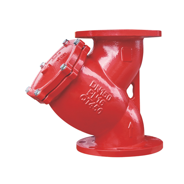
Grooved Y Strainer for Fire Protection Pipelines
A grooved Y strainer is a pipeline filtration device that combines the proven Y-body strainer geometry with Victaulic-compatible grooved end connections, enabling fast, tool-efficient installation into grooved fire protection and industrial pipeline systems. Where a flanged Y strainer requires gasket alignment, flange bolt patterns and calibrated torque wrench work at every joint, a grooved Y strainer connects to grooved-end pipework using a standard mechanical coupling and two bolts — assembled by one installer in under two minutes per joint, with no hot work and no precision alignment required.
CA-FIRE’s grooved Y strainer filters solid particles, pipe scale, weld spatter and construction debris from fire protection pipelines before they can reach and damage pumps, alarm valves, pressure-reducing valves and control valves downstream. Available in DN50–DN200 with Victaulic IPS-compatible grooved ends, it is the natural choice for grooved fire protection systems on fast-track construction projects, retrofit installations and any application where minimising installation time and future maintenance downtime are design priorities.
Grooved Y Strainer Technical Specifications
| Parameter | Specification |
|---|---|
| Product Type | Grooved Y Strainer — Victaulic IPS Compatible |
| Nominal Pressure | 1.6 MPa (PN16) |
| Nominal Diameter | DN50–DN200 |
| Strength Test Pressure | 2.4 MPa |
| Applicable Medium | Water and equivalent fluid media |
| Medium Temperature | 4–70 °C |
| Body Material | Ductile iron, epoxy coated |
| Screen Material | Stainless steel (SS304) perforated mesh |
| Connection Method | Grooved ends — Victaulic IPS standard |
| Screen Access | Bolted end cap — no pipe disconnection required |
| Certifications | GB/T standard, ISO 9001, CE |
Structural Length by Nominal Diameter
| Nominal Diameter | Structural Length (mm) |
|---|---|
| DN50 | 197 |
| DN65 | 240 |
| DN80 | 270 |
| DN100 | 300 |
| DN125 | 335 |
| DN150 | 385 |
| DN200 | 470 |
Grooved Y Strainer Key Features
Grooved End Connection — Installation Without Compromise
The defining advantage of the grooved Y strainer over its flanged equivalent is the speed and simplicity of connection. Each grooved joint requires just a coupling gasket, a two-piece coupling housing and two bolts. There is no flange face alignment, no gasket centering and no cross-pattern torque sequence — the coupling drops into the grooves on both the strainer end and the pipe end, the bolts are run up finger-tight and then snugged with a socket wrench until the housing pads make metal-to-metal contact. The entire joint is mechanically complete and ready for pressure testing. On projects where grooved Y strainers are installed at multiple pump inlets, valve stations or riser levels, the cumulative time saving over flanged installation across all joints is substantial.
The grooved connection also makes the grooved Y strainer significantly easier to remove for screen cleaning and maintenance than a flanged equivalent. To remove a flanged strainer, all flange bolts must be broken loose, the pipe flanges separated and the strainer withdrawn — a task requiring two people and generating considerable mess in a pressurised system environment. To remove a grooved Y strainer, two coupling bolts are removed, the coupling housing halves are slid back, and the strainer slides out of the pipeline in seconds. Screen cleaning and reinsertion can be completed by a single technician in the time it would take to break loose the first flanged joint on an equivalent flanged strainer.
SS304 Stainless Steel Screen — Reliable Long-Term Filtration
The cylindrical SS304 stainless steel perforated screen inside the grooved Y strainer captures solid particles while maintaining a large open area that keeps pressure drop low even as the screen accumulates debris. The SS304 construction is chemically inert to chlorinated water, mild scale inhibitors and foam fire suppression concentrates, maintaining dimensional stability and consistent mesh aperture through repeated wet-dry cycles and cleaning operations. Screen replacement — when eventually required after years of service — involves removing the end cap, withdrawing the screen cylinder and inserting a replacement, without disturbing the grooved connections to the pipeline.
Compact Y-Body Profile — Fits Congested Pipe Routes
The Y-body geometry of the grooved Y strainer positions the screen chamber at an oblique angle to the main flow bore, creating a filtration surface area larger than the pipe bore while keeping the overall body envelope compact. In grooved fire protection systems — where pipework is often installed in congested ceiling voids, riser shafts and plant rooms alongside electrical conduit, ductwork and structural members — the compact profile of the grooved Y strainer avoids the clash issues that larger basket strainer bodies frequently generate at tight installation locations. The absence of projecting flange rings further reduces the lateral clearance required compared to flanged alternatives.
Gravity Debris Settlement — Extended Cleaning Intervals
During normal pipeline operation, the oblique orientation of the grooved Y strainer’s screen chamber causes collected debris to migrate toward the bottom of the screen under gravity, concentrating it in the drain cap area and away from the active filtration zone. This self-segregation of debris extends the effective cleaning interval by keeping the majority of the screen surface clear, and simplifies cleaning when the cap is eventually opened — most of the accumulated debris drains out with the water when the cap is removed, rather than requiring brushing or flushing to dislodge.
Epoxy-Coated Ductile Iron Body
The grooved Y strainer body is cast from GGG50 ductile iron and coated inside and out with fusion-bonded epoxy. GGG50 ductile iron provides the tensile strength and impact resistance required to withstand water hammer and pressure surge events in fire protection pipelines — particularly during fire pump start-up, where pressure transients can exceed twice the system static pressure. The epoxy coating protects the body from internal corrosion in stagnant fire water and from external corrosion in the humid plant room and riser environments where grooved fire protection systems are typically installed.
Grooved Y Strainer Applications
[IMAGE: grooved Y strainer installed pump inlet grooved fire protection pipeline — CA-FIRE] [IMAGE ALT TEXT: grooved Y strainer installed at pump suction fire protection pipeline — CA-FIRE Victaulic compatible]
Fire Pump Suction Protection on Grooved Systems
Installing a grooved Y strainer on the suction side of fire pumps, jockey pumps and booster pumps on fully grooved pipeline systems protects impellers and mechanical seals from the particulate contamination that causes accelerated wear and premature pump failure. The grooved connection matches directly to the grooved pump suction flange adapter, maintaining a fully grooved system from tank or main connection through to pump outlet — with no need for a flanged spool piece or transition fitting simply to accommodate a flanged strainer body.
Alarm Valve and Deluge Valve Inlet Protection
Alarm valves, deluge valves and pre-action valve assemblies contain internal clapper seats, pilot trim and diaphragm components that must remain clean and undamaged to function correctly. A grooved Y strainer installed immediately upstream captures pipe scale, weld spatter and commissioning debris before it reaches these precision components. The ability to remove the grooved Y strainer for screen inspection without disconnecting the pipeline simplifies pre-commissioning flushing verification and annual inspection access.
Pressure-Reducing Valve Stations
On grooved fire protection risers in high-rise buildings where pressure-reducing valve stations are installed at regular floor intervals, a grooved Y strainer at each PRV station provides targeted filtration protection for the PRV pilot circuit and diaphragm seat. The grooved connection reduces installation time at each floor station and allows individual PRV stations to be isolated and the strainer screen removed for inspection without draining the entire riser.
Retrofit into Existing Grooved Systems
The grooved Y strainer is the straightforward filtration solution for retrofit upgrades to existing grooved pipeline systems where pipe filtration was not originally provided or where original strainers require replacement. Because the grooved connection requires no pipe modification — just cutting two coupling grooves if the pipe is not already grooved at the installation point — the grooved Y strainer can be inserted into an existing pipeline with minimal disruption to the system and surrounding structure.
Fast-Track Construction and Modular Builds
On construction programmes using prefabricated modular plant rooms and pre-assembled pipework spools, the grooved Y strainer integrates directly into pre-grooved spool assemblies during off-site fabrication, arriving on site ready to connect. This eliminates the on-site bolting work associated with flanged strainer installation and allows the complete spool assembly to be pressure-tested and inspected before leaving the fabrication shop.
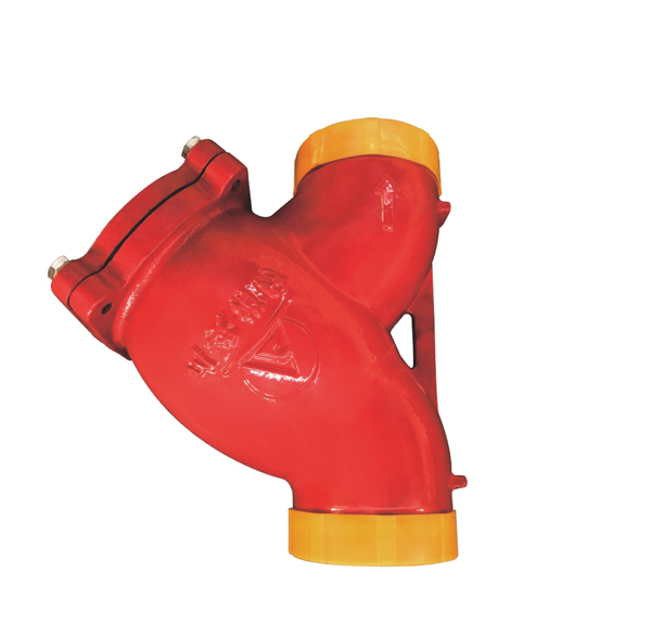
Grooved Y Strainer vs. Flanged Y Strainer — Which to Specify?
| Grooved Y Strainer | Flanged Y Strainer | |
|---|---|---|
| Connection method | Mechanical coupling — 2 bolts | Bolted flange — multiple bolts |
| Installation speed | ✓ Fast — minutes per joint | Slower — alignment and torquing |
| Available size range | DN50–DN200 | DN50–DN300 |
| Future disassembly | ✓ Easy — 2 bolts per joint | Multiple flange bolts per joint |
| Joint rigidity | Good | ✓ Superior |
| Retrofit suitability | ✓ Excellent | Good |
| Fully grooved system fit | ✓ Seamless | Requires transition fitting |
| Screen access | Without disconnecting pipe | Without disconnecting pipe |
Specify the grooved Y strainer when the pipeline system uses grooved connections throughout, when installation programme speed is a priority, or when ease of future screen removal and maintenance access is important. Specify the flanged Y strainer when the pipeline uses flanged connections, when sizes above DN200 are required, or when flanged connections are specified as a project standard.
Installation Guidelines
Pre-Installation Checklist
- Confirm the grooved Y strainer nominal diameter and groove standard (IPS) match the pipeline pipe outside diameter and coupling specification.
- Check pipe groove dimensions at the installation location — groove width and depth must be within the coupling manufacturer’s tolerance.
- Confirm installation orientation — the screen cap must point downward or at a downward angle; never upward.
- Inspect the body, screen, end cap and grooved faces for transit damage before installation.
- Arrange temporary bypass provisions if the pipeline must remain live during installation.
Grooved Joint Assembly
Lubricate the mechanical coupling gaskets with the coupling manufacturer’s approved EPDM-compatible lubricant — do not use petroleum-based products on EPDM gaskets. Slide the gasket centrally over one pipe end and position the grooved Y strainer between the two pipe ends with the flow arrow aligned to the pipeline flow direction. Fit the coupling housing halves over both grooved ends, insert the coupling bolts and tighten evenly in alternating sequence until the housing pads achieve firm metal-to-metal contact at both joints. Check both couplings for uniform gasket seating before pressurising.
Initial Commissioning Flush
Before putting the grooved Y strainer into permanent service, flush the upstream pipeline thoroughly with the strainer screen either removed or protected by a temporary bypass. Construction debris, weld spatter and pipe scale shed during initial system fill and flushing will load a new screen rapidly and may cause pressure drop issues during early system commissioning. After the initial flush is complete, install the permanent screen, commission the system and inspect the screen again after the first two to four weeks of operation.
Post-Installation Pressure Test
Conduct a hydrostatic test to system test pressure and check for leakage at both grooved couplings and the screen end cap. Any leakage at the grooved joints should be corrected by verifying gasket seating and re-torquing the coupling bolts before retesting. Document test pressures, hold times and results in the project commissioning record.
Maintenance Schedule
Monthly — Visual Inspection
- Inspect the grooved Y strainer body, grooved coupling joints and screen cap for leaks, corrosion or physical damage.
- Check grooved coupling bolts for looseness — a single re-torque may be required during the first months after installation as the coupling gasket beds in under system pressure.
- Where differential pressure gauges are installed across the strainer, check for rising differential indicating screen loading.
Quarterly — Screen Removal and Cleaning
- Isolate and depressurise the strainer via the drain cap or an upstream isolation valve.
- Release the two coupling bolts on one grooved joint, slide the coupling housing back and withdraw the grooved Y strainer from the line.
- Remove the screen cap bolts, extract the SS304 screen and inspect for holes, tears or permanent deformation — replace immediately if any damage is found.
- Flush the screen clean with running water or low-pressure compressed air from inside outward.
- Inspect the end cap gasket and replace if compression set or cracking is observed.
- Reinstall, reconnect the grooved coupling and pressure-test the joint before restoring system pressure.
Annual — Full Inspection
- Conduct a full internal inspection of the body, screen housing and cap sealing faces.
- Pressure-test to 2.4 MPa and record results.
- Replace the SS304 screen element preventively every 3–5 years, or earlier if repeated cleaning has not fully restored screen open area.
- Replace grooved coupling gaskets every 5 years as a preventive measure regardless of apparent condition.
Grooved Y Strainer — Frequently Asked Questions
What is a grooved Y strainer?
A grooved Y strainer is a Y-body pipeline filter with Victaulic IPS-compatible grooved end connections instead of bolted flanges. It filters solid particles from flowing fluid to protect downstream equipment — pumps, valves, instrumentation — in exactly the same way as a flanged Y strainer, but connects to grooved-end pipeline systems using mechanical couplings rather than flange bolts. This makes the grooved Y strainer faster to install, easier to remove for maintenance and seamlessly compatible with fully grooved fire protection pipeline systems.
How does a grooved Y strainer differ from a flanged Y strainer?
The filtration performance, body geometry and screen materials of the grooved and flanged Y strainer are identical. The difference is entirely in the end connection method. The flanged Y strainer uses bolted flange joints — permanent, high-integrity connections suitable for all pipe sizes up to DN300. The grooved Y strainer uses mechanical couplings — faster to install and easier to disassemble, but limited to DN200 in CA-FIRE’s current range. For fully grooved pipeline systems, the grooved Y strainer is the seamless specification choice; for flanged systems or larger pipe sizes, the flanged Y strainer is specified instead.
In which orientation should a grooved Y strainer be installed?
The screen cap of the grooved Y strainer should always point downward or at a downward angle — never upward. Downward orientation allows collected debris to settle by gravity to the bottom of the screen chamber, away from the main flow path, extending the cleaning interval and ensuring debris drains cleanly when the cap is opened for maintenance. Installing the screen cap upward causes debris to accumulate against the flow area, increasing pressure drop and making cleaning more difficult.
What coupling standard is used for the grooved connections?
CA-FIRE’s grooved Y strainer is machined to IPS (Iron Pipe Size) grooved standard, compatible with Victaulic and all major IPS-standard grooved coupling manufacturers. Always confirm the pipe outside diameter and groove standard with your coupling supplier before installation to ensure dimensional compatibility.
Can the grooved Y strainer be used with foam fire suppression systems?
Yes. The EPDM coupling gaskets and SS304 stainless steel screen of the grooved Y strainer are compatible with water and aqueous foam fire suppression mixtures including AFFF and protein foam concentrates. Confirm specific foam concentrate compatibility with CA-FIRE’s technical team for high-concentration or fluorine-free foam formulations.
Why Specify CA-FIRE’s Grooved Y Strainer?
CA-FIRE manufactures the grooved Y strainer to the same dimensional tolerances and quality standards as the flanged range, ensuring that grooved couplings seat correctly on every valve end without on-site fitting adjustment. Each strainer undergoes factory hydrostatic pressure testing to 2.4 MPa before despatch, and the SS304 screen is dimensionally verified against the specified mesh aperture and open area specification.
The grooved DN50–DN200 range pairs directly with CA-FIRE’s full grooved gate valve series — grooved signal gate valve, grooved NRS gate valve and grooved rising stem gate valve — enabling engineers and contractors to specify a complete, fully grooved fire protection valve and strainer package from a single manufacturer, with consistent dimensional standards, unified technical support and simplified procurement.
Get a Quote
Contact CA-FIRE for pricing, technical drawings, project specifications or OEM supply enquiries. Our engineering team responds within one business day.
- Email: sales@ca-fire.com
- Mobile / WhatsApp: +86 13400715622
- WeChat: 404863577
- Website: www.ca-fire.com
Related products: Flanged Y Type Strainer · Grooved Signal Gate Valve · Grooved NRS Gate Valve · Gate Valve Series · Fire Alarm Valves
For pipeline strainer selection, installation and maintenance requirements, refer to NFPA 25.