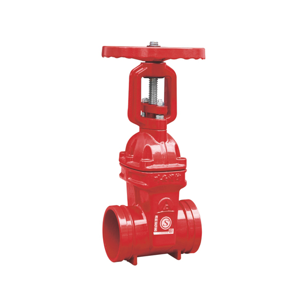
Rising Stem Gate Valve — Grooved End Fire Protection Design
A rising stem gate valve is a fire protection isolation valve whose externally threaded stem travels visibly upward through the yoke as the valve opens, and retracts as it closes. At any point during operation, the position of the stem above the handwheel directly indicates how far open the valve is — no gauges, no dial indicators, no electronic monitoring required. When the stem is fully extended, the valve is fully open. When the stem is flush with the handwheel nut, the valve is fully closed. This unambiguous, mechanical position indication is visible from across a plant room, making the rising stem gate valve the first choice for fire protection installations where rapid visual confirmation of valve status is operationally critical.
CA-FIRE’s grooved end rising stem gate valve (Model: ZSZF8-Q-50~250-16-M) combines this inherently reliable stem indication with Victaulic-compatible grooved end connections and a rubber-encapsulated resilient wedge — delivering fast installation, long-term sealing performance and code-compliant visual indication in a single lightweight package. Available in DN50–DN250, it is engineered for automatic fire sprinkler systems, standpipe systems and fire hydrant supply networks across commercial, industrial and infrastructure applications.
Rising Stem Gate Valve Technical Specifications
| Parameter | Specification |
|---|---|
| Product Model | ZSZF8-Q-50~250-16-M |
| Valve Type | Rising Stem Gate Valve — Grooved End |
| Nominal Pressure | 1.6 MPa (PN16) |
| Nominal Diameter | DN50–DN250 |
| Strength Test Pressure | 6.4 MPa |
| Seal Test Pressure | 3.2 MPa |
| Applicable Medium | Water, foam fire suppression mixture |
| Medium Temperature | 4–70 °C |
| Connection Method | Grooved ends — Victaulic IPS compatible |
| Stem Design | Rising Stem — externally threaded, travels through yoke |
| Stem Indication | Fully open: stem fully extended / Fully closed: stem flush |
| Wedge Type | Resilient wedge, EPDM rubber-encapsulated |
| Body Material | Ductile iron, fusion-bonded epoxy coated |
| Certifications | GB 12736, ISO 9001, CE |
Structural Length by Nominal Diameter
| Nominal Diameter | Structural Length (mm) |
|---|---|
| DN50 | 150 |
| DN65 | 160 |
| DN80 | 175 |
| DN100 | 185 |
| DN125 | 205 |
| DN150 | 212 |
| DN200 | 248 |
| DN250 | 263 |
Rising Stem Gate Valve Key Features
Mechanical Stem Indication — No Electronics Required
The rising stem gate valve provides position indication through pure mechanical means. As the handwheel rotates, the externally threaded stem translates linearly through the yoke — extending upward when opening, retracting when closing. The length of exposed stem above the yoke is a direct, proportional indicator of valve opening degree. This mechanical indication never requires calibration, never needs a battery, never loses signal continuity and cannot be accidentally disabled. In a fire emergency, when electronic systems may be impaired, the rising stem gate valve’s position status remains immediately readable by anyone in the plant room — including first responders unfamiliar with the building’s BMS or FACP interface.
Grooved End Connection — Speed Without Compromise
Pairing rising stem technology with Victaulic IPS-compatible grooved ends produces a valve that offers the visual indication advantages of a flanged OS&Y design in a lighter, faster-installing package. The grooved rising stem gate valve connects to grooved-end pipeline systems with a standard mechanical coupling and two bolts — no flange alignment, no gasket orientation, no cross-pattern bolt torquing sequence. On multi-storey fire protection installations where zone control valves are installed at every floor level, the cumulative installation time saving over flanged alternatives is substantial. The grooved joint also allows the rising stem gate valve to be removed and reinstalled for maintenance or replacement without cutting the pipeline.
EPDM Resilient Wedge for Consistent Shut-Off
The EPDM rubber-encapsulated resilient wedge delivers bubble-tight sealing against the precision-machined valve seats across the full operating pressure range. The compliant rubber surface accommodates minor seat irregularities and thermal movement, eliminating the scoring and corrosion welding risks associated with metal-to-metal wedge designs. Operating torque remains low and predictable throughout the valve’s service life — the rising stem gate valve can be fully opened or closed by a single operator without excessive effort, even after years of service in a static fire protection installation.
Full-Bore Flow Path — Hydraulic Efficiency
When fully open, the rising stem gate valve presents an unobstructed full-bore flow path through the body. The wedge is completely retracted into the body cavity, and water flows straight through without any internal obstructions, directional changes or velocity transitions. In fire protection hydraulic design, this translates to negligible equivalent pipe length across the valve — typically less than 0.5 metres — ensuring that zone control valves do not introduce hydraulic penalties that must be compensated elsewhere in the system design.
Robust Yoke Construction for Long Service Life
The external yoke of the rising stem gate valve is cast integrally with the bonnet, forming a single rigid structure that supports the stem under both operating torque and axial stem load. The yoke geometry is designed to protect the rising stem threads from accidental mechanical damage during routine maintenance activity in the valve’s vicinity — a practical consideration in busy plant rooms where adjacent equipment is regularly worked on. The entire valve exterior, including the yoke, receives fusion-bonded epoxy coating for corrosion protection in humid fire protection environments.
Rising Stem Gate Valve Applications
[IMAGE: rising stem gate valve grooved installed fire sprinkler zone control — CA-FIRE] [IMAGE ALT TEXT: rising stem gate valve grooved end installed fire sprinkler zone control — CA-FIRE ZSZF8-M]
Fire Sprinkler Zone Control Valves
The rising stem gate valve is specified as a zone control valve on wet-pipe, dry-pipe and pre-action sprinkler systems where direct visual confirmation of valve position during inspections, impairment procedures and maintenance operations is required. NFPA 13 mandates that sprinkler system control valves be of an indicating type — the rising stem gate valve satisfies this requirement through its mechanical stem indication, with no additional indicator devices needed. Building fire safety managers can perform a visual sweep of all zone control valve positions in a riser shaft in seconds, without accessing any monitoring system.
Standpipe System Isolation
Used as floor isolation and sectional control valves on Class I, II and III standpipe systems in high-rise buildings, hotels and large institutional facilities. The rising stem gate valve’s clear open/closed stem indication allows firefighting crews to rapidly assess which standpipe zones are active during fire operations, making tactical decisions faster and more confidently. The lightweight grooved body simplifies installation on standpipe risers in stairwells and riser shafts where working space is restricted.
Fire Pump Room Isolation Valves
Installed on fire pump suction and discharge connections as primary isolation valves, the rising stem gate valve allows pump room operators to visually confirm valve position during weekly, monthly and annual fire pump tests without consulting the building management system. During pump room inspections by fire authorities, the rising stem’s clear visual indication demonstrates system readiness immediately and unambiguously.
Fast-Track Construction Projects
On construction programmes where fire protection systems must be installed and commissioned under compressed schedules, the combination of grooved end connections and rising stem indication in a single valve reduces both installation time and post-installation inspection complexity. Grooved joints install faster than flanged joints; the rising stem eliminates the need to install separate position indicator accessories; and the EPDM wedge delivers reliable sealing from first pressurisation without requiring commissioning adjustments.
Retrofit Upgrades to Existing Grooved Systems
Where existing grooved fire protection pipelines require upgraded zone control valves — replacing older butterfly valves or worn gate valves — the grooved rising stem gate valve installs directly into the existing pipeline without modification. The mechanical coupling joints allow removal and replacement of valves in occupied buildings with minimal system downtime and no hot work, enabling live-building upgrades that would be impractical with flanged alternatives.
Rising Stem Gate Valve vs. Non-Rising Stem Gate Valve — Key Differences
| Rising Stem Gate Valve | Non-Rising Stem Gate Valve | |
|---|---|---|
| Position indication | Mechanical stem — visible at a glance | Bonnet dial indicator |
| Overhead clearance needed | Yes — stem extends above handwheel | Minimal — stem stays in place |
| NFPA 13 indicating valve | ✓ Yes — stem provides direct indication | ✓ Yes — via dial indicator |
| Suitable for confined spaces | Less suitable | ✓ Preferred |
| Above-ground open access | ✓ Preferred | Suitable |
| External stem protection | Exposed — avoid impact hazards | Protected inside bonnet |
| Maintenance access | Stem and packing externally accessible | Stem threads inside body |
| Grooved end available | ✓ Yes — DN50–DN250 | ✓ Yes — DN50–DN250 |
When to specify: Choose the rising stem gate valve for above-ground locations where direct, unambiguous visual position indication without any secondary indicator device is the priority — particularly where fire authority inspectors or firefighting crews may need to rapidly assess valve status. Choose the non-rising stem gate valve where overhead space is restricted or for underground and pit-mounted applications.
Installation Guidelines
Pre-Installation Checklist
- Verify the rising stem gate valve nominal diameter, pressure rating and groove standard match the pipeline and coupling specification.
- Measure the available overhead clearance above the valve — the stem must be able to travel the full open distance above the handwheel yoke without obstruction. Allow at minimum the valve’s nominal diameter plus 200 mm above the top of the yoke.
- Inspect the valve body, EPDM wedge, stem, yoke and grooved faces for any transit damage before installation.
- Confirm the pipeline has been thoroughly flushed before the rising stem gate valve is installed — pipe scale and weld spatter can damage the resilient wedge on first closure.
Grooved End Assembly
Lubricate the mechanical coupling gaskets with the coupling manufacturer’s approved EPDM-compatible lubricant. Position the rising stem gate valve centrally between the two pipe ends, ensuring the valve body flow direction arrow aligns with the pipeline flow direction. Fit the coupling housing halves over both grooved ends — valve end and pipe end — and insert the coupling bolts. Tighten the bolts evenly in alternating sequence until the coupling housing pads achieve firm metal-to-metal contact on both sides of the joint. Check both couplings for uniform gasket seating before pressurising the system.
First Operation and Commissioning
Open the rising stem gate valve slowly to full open and visually confirm the stem extends to its full travel length above the yoke. The stem should travel smoothly without binding or unusual resistance throughout its full range. Close the valve fully and confirm the stem retracts completely, with its upper end flush with or below the top of the handwheel nut. Conduct the hydrostatic pressure and seal test, then reopen to full open and lock the valve in the open position with an approved locking device.
Post-Installation Testing
- Hydrostatic pressure test to 3.2 MPa — hold for the required duration and check for leakage at the valve body, grooved couplings, bonnet and stem packing.
- Cycle the rising stem gate valve fully open and closed to confirm smooth operation and correct stem travel at both end positions.
- Confirm rising stem position clearly indicates both fully open and fully closed valve status.
- Lock valve open, attach identification tag, and record installation and test details in the fire protection system commissioning log.
Maintenance Schedule
Maintenance must comply with NFPA 25 and applicable local fire protection authority requirements. The externally accessible stem and packing of the rising stem gate valve simplify several routine maintenance tasks compared to non-rising stem designs.
Monthly — Visual Inspection
- Confirm the rising stem is fully extended — valve is fully open.
- Check the valve is locked or sealed in the open position.
- Inspect the stem threads, yoke and packing gland area for corrosion, mechanical damage or signs of stem packing leakage.
- Examine the grooved coupling joints and valve body exterior for leaks or corrosion.
Quarterly — Operational Exercise
- Exercise the rising stem gate valve through its full open-close-open travel and confirm smooth, consistent torque with no binding or stiffness in the stem travel.
- Inspect the stem thread condition — clean and apply a light coat of water-resistant grease to the exposed stem threads if any corrosion or dryness is observed.
- Check grooved coupling bolts for looseness and retighten if required.
Annual — Comprehensive Check
- Inspect the packing gland and stem packing for wear or leakage — re-tighten the gland nut or repack as required.
- Inspect the EPDM wedge for surface cuts, compression set or chemical deterioration by closing the valve and examining the wedge through the valve bore if the system is drained.
- Conduct a full pressure and seat leakage test to 3.2 MPa and record results.
- Replace packing and coupling gaskets preventively every 2–3 years.
- Lubricate stem threads and stem nut with fresh water-resistant grease after cleaning.
Rising Stem Gate Valve — Frequently Asked Questions
What is a rising stem gate valve?
A rising stem gate valve is a gate valve in which the operating stem is threaded on its exterior and passes through a nut fixed in the yoke above the valve bonnet. As the handwheel is turned to open the valve, the stem rises upward through the yoke, extending visibly above the handwheel. As the valve closes, the stem retracts. The position of the stem above the yoke at any moment directly indicates the valve’s open/close status — fully extended means fully open, flush means fully closed. This mechanical position indication is the defining operational advantage of the rising stem gate valve in fire protection applications.
How does a rising stem gate valve differ from an OS&Y valve?
An OS&Y valve — Outside Screw and Yoke — is a specific type of rising stem gate valve. All OS&Y valves are rising stem gate valves, but not all rising stem gate valves are described as OS&Y in every market or specification system. The OS&Y designation is most commonly used in North American fire protection specifications, particularly in NFPA 13 and NFPA 25 documentation. In international markets and general engineering applications, the same design is more frequently described simply as a rising stem gate valve. CA-FIRE’s grooved rising stem gate valve meets the design intent and operational requirements of both designations.
Does this rising stem gate valve meet NFPA 13 indicating valve requirements?
Yes. NFPA 13 requires fire protection control valves to be of an indicating type — the open or closed status of the valve must be visually determinable without operating the valve. The rising stem gate valve satisfies this requirement directly through the mechanical position of the stem, which provides unambiguous, continuously visible indication of valve status. No secondary position indicator accessory is required when a rising stem gate valve is used.
When should I choose a grooved rising stem gate valve over a flanged OS&Y valve?
Choose the grooved rising stem gate valve when the pipeline system uses grooved connections throughout, when installation speed is a programme priority, or when future maintenance access for valve removal and replacement without pipe cutting is important. Choose the flanged OS&Y valve when the pipeline uses flanged connections, when primary riser connections at DN300 and above are required, or when project specifications explicitly call for flanged end connections. Both provide equivalent visual stem indication and fire protection performance.
What is the maximum size available in grooved configuration?
CA-FIRE’s grooved end rising stem gate valve is available from DN50 to DN250. For larger diameter applications at DN300 to DN400, CA-FIRE’s flanged OS&Y gate valve provides equivalent rising stem indication with flanged end connections. Contact CA-FIRE’s engineering team for project-specific size requirements.
Why Specify CA-FIRE’s Grooved Rising Stem Gate Valve?
CA-FIRE designs the rising stem gate valve for the specific demands of fire protection service — long static open periods followed by infrequent but critical operation during testing, maintenance and emergency response. Every valve undergoes factory hydrostatic testing to 6.4 MPa, seal testing to 3.2 MPa and full stem travel verification before despatch. The EPDM wedge encapsulation, fusion-bonded epoxy body coating and stainless steel stem are specified to perform reliably across a 25+ year design service life.
With ISO 9001 certified manufacturing and GB 12736 product certification, CA-FIRE’s rising stem gate valve is accepted by fire protection authorities across more than 50 countries. The grooved DN50–DN250 range pairs seamlessly with CA-FIRE’s grooved signal gate valve for applications requiring additional electronic tamper switch monitoring, and with the flanged OS&Y gate valve series for larger diameter or flanged-connection applications.
Get a Quote
Contact CA-FIRE for pricing, technical drawings, project specifications or OEM supply enquiries. Our engineering team responds within one business day.
- Email: sales@ca-fire.com
- Mobile / WhatsApp: +86 13400715622
- WeChat: 404863577
- Website: www.ca-fire.com
Related products: OS&Y Gate Valve — Flanged · Grooved NRS Gate Valve · Grooved Signal Gate Valve · Gate Valve Series · Fire Alarm Valves
For rising stem gate valve inspection and testing requirements in fire protection service, refer to NFPA 25.