
Grooved Gate Valve for Fire Protection — Fast-Install Supervisory Design
The grooved gate valve is a fire protection control valve that uses mechanical grooved couplings instead of bolted flanges, enabling significantly faster installation and easier future maintenance than traditional flanged valves. A grooved gate valve connects to grooved-end pipe sections using a simple coupling and gasket assembly — no welding, no flange drilling, no precision alignment. This speed and flexibility of installation has made the grooved gate valve the preferred choice for fire sprinkler contractors working on fast-track construction programmes and retrofit projects.
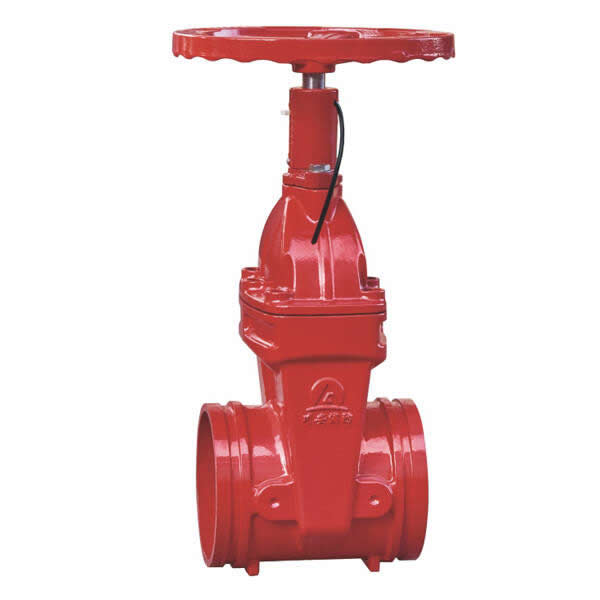
CA-FIRE’s grooved gate valve (Model: ZSXZF8-Q-50~250-16) is a non-rising stem, supervisory gate valve with an integrated tamper switch, engineered for automatic fire sprinkler systems, fire hydrant mains and standpipe installations. Available in DN50–DN250 with Victaulic-compatible grooved end connections, it delivers the supervisory monitoring required by NFPA 13 in a lightweight, compact body that installs in a fraction of the time of a flanged equivalent.
Grooved Gate Valve Technical Specifications
| Parameter | Specification |
|---|---|
| Product Model | ZSXZF8-Q-50~250-16 |
| Valve Type | Grooved Gate Valve — Non-Rising Stem with Supervisory Switch |
| Nominal Pressure | 1.6 MPa (PN16) |
| Nominal Diameter | DN50–DN250 |
| Strength Test Pressure | 6.4 MPa |
| Seal Test Pressure | 3.2 MPa |
| Applicable Medium | Water, foam fire suppression mixture |
| Medium Temperature | 4–70 °C |
| Switch Contact Capacity | DC 24V / 0.5A |
| Signal Transmission Delay | < 0.5 seconds |
| Connection Method | Grooved ends — Victaulic-compatible IPS standard |
| Stem Design | Non-Rising Stem (NRS) with dial position indicator |
| Wedge Type | Resilient wedge, rubber-encapsulated |
| Certifications | GB 15930, ISO 9001, CE |
Structural Length by Nominal Diameter
| Nominal Diameter | Structural Length (mm) |
|---|---|
| DN50 | 150 |
| DN65 | 160 |
| DN80 | 175 |
| DN100 | 185 |
| DN125 | 205 |
| DN150 | 212 |
| DN200 | 248 |
| DN250 | 263 |
Grooved Gate Valve Key Features
Victaulic-Compatible Grooved Connection — Install in Minutes
The defining advantage of a grooved gate valve over a flanged design is installation speed. A grooved coupling joint requires no gasket alignment, no bolt pattern matching and no torque wrench — the coupling housing drops over the pipe grooves, the bolts are tightened finger-tight and then snugged with a standard socket wrench in under two minutes per joint. On a large fire protection project with dozens of control valve locations, the time saving of specifying a grooved gate valve over flanged alternatives can amount to days of installation labour. The grooved joint also allows the valve to be removed and reinstalled for maintenance without cutting the pipeline — simply undo the two coupling bolts and slide the valve out.
Supervisory Switch with DC 24V Output
Every CA-FIRE grooved gate valve is supplied complete with a factory-fitted supervisory tamper switch. The switch monitors valve position continuously and transmits a DC 24V signal to the fire alarm control panel the moment the valve begins to close from its fully open position. Signal transmission occurs in under 0.5 seconds, providing near-instantaneous supervisory alarm capability. The DC 24V / 0.5A dry contact output is compatible with the supervisory input circuits of all mainstream fire alarm control panels manufactured to EN 54, UL 864 and equivalent standards.
Lightweight Compact Body — Easy Handling on Site
The grooved gate valve body is cast from high-grade ductile iron and finished with fusion-bonded epoxy inside and out, delivering excellent corrosion resistance at a significantly lower weight than an equivalent flanged valve. The absence of heavy flanges and flange bolting reduces the valve weight by up to 30% compared to a flanged equivalent — making the grooved gate valve significantly easier to handle, position and install, particularly at height or in confined riser enclosures.
Dial Position Indicator for Visual Confirmation
The bonnet-mounted dial indicator displays the valve’s open/close position at all times, giving maintenance personnel an instant visual check of valve status without having to consult the FACP. This dual monitoring capability — visual via the dial and electronic via the supervisory switch — ensures valve status can be confirmed by any building personnel during routine inspections, not only by those with FACP access.
Resilient Wedge — Consistent Sealing Performance
The rubber-encapsulated resilient wedge delivers a consistent, bubble-tight seal across the full DN50–DN250 size range and throughout the 4–70°C operating temperature range. Unlike metal wedge designs, the resilient coating self-compensates for minor thermal movement and seat wear, maintaining sealing integrity over the full service life of the valve without periodic seat adjustment. Operating torque remains low and consistent, ensuring the valve can be opened or closed quickly and easily under all service conditions.
Grooved Gate Valve Applications
[IMAGE: grooved gate valve installed on fire sprinkler riser Victaulic coupling — CA-FIRE] [IMAGE ALT TEXT: grooved gate valve installed fire sprinkler riser Victaulic coupling supervisory — CA-FIRE]
Retrofit and Upgrade Projects
The grooved gate valve is the installer’s first choice for retrofit fire protection projects where existing pipelines are already grooved, or where minimum disruption to occupied buildings is essential. Since grooved joints require no hot work and can be made in confined spaces with hand tools only, the grooved gate valve can be installed in locations where welding or flange bolting would be impractical. System upgrades that previously required extended shutdowns can often be completed in a single working day using grooved gate valves.
High-Rise Building Sprinkler Systems
In high-rise construction, where fire protection pipelines are installed floor by floor in parallel with other trades, the installation speed of the grooved gate valve directly reduces programme time. Zone control valves on each floor can be installed and the system tested and commissioned faster than with flanged alternatives, helping contractors meet handover milestones. The lighter weight of the grooved gate valve also eases handling in lift lobbies and stairwells where access is restricted.
Commercial and Institutional Buildings
Shopping centres, hotels, hospitals, schools and office buildings — where fire protection systems must be installed with minimum disruption to ongoing occupancy — benefit from the clean, tool-friendly installation of the grooved gate valve. The absence of flange gaskets and bolt patterns reduces installation errors and the risk of joint leakage, while the built-in supervisory switch ensures the completed installation meets NFPA 13 supervisory requirements from day one.
Industrial Pipe Racks and Process Areas
In industrial facilities where fire water pipelines share congested pipe racks with process pipework, the compact body and grooved connections of the grooved gate valve take up less lateral space than flanged valves and require no bolt clearance zones around the connection. The valve can be removed for maintenance without disturbing adjacent pipework — an important practical advantage in densely packed pipe racks.
Fire Suppression Systems for Foam Applications
The grooved gate valve’s wetted components — resilient wedge, sealing gaskets and epoxy-coated body — are fully compatible with aqueous film-forming foam (AFFF) and protein foam fire suppression concentrates in addition to water. This makes it suitable for use on foam system supply mains in aircraft hangars, fuel storage facilities and other applications where foam suppression is required alongside or instead of water-only sprinkler systems.
Grooved Gate Valve vs. Flanged Gate Valve — Which to Specify?
| Grooved Gate Valve | Flanged Gate Valve | |
|---|---|---|
| Installation speed | ✓ Fast — coupling installs in minutes | Slower — gasket, bolt alignment, torquing |
| Pipe size range | DN50–DN250 | DN50–DN400 |
| Future disassembly | ✓ Easy — remove two coupling bolts | Requires flange bolt removal |
| Joint integrity under surge | Good | ✓ Superior — bolted flanges |
| Weight | ✓ Lighter | Heavier |
| Hot work required | ✓ None | None (bolted) |
| Retrofit suitability | ✓ Excellent | Good |
| Available sizes at CA-FIRE | DN50–DN250 | DN50–DN300 |
Specify the grooved gate valve when installation speed, site flexibility and ease of future maintenance are the primary drivers. Specify the flanged gate valve for primary riser and main supply connections at DN300 and above, or where flanged connections are specified as a project standard.
Installation Guidelines
Pre-Installation Checklist
- Confirm the grooved gate valve nominal diameter matches the pipe outside diameter and groove standard (IPS, ISO or AWWA as applicable).
- Verify the pipe groove dimensions — groove width, groove depth and pipe outside diameter — are within the coupling manufacturer’s tolerance for the coupling being used.
- Check the valve body, supervisory switch housing, grooved faces and resilient wedge for any transit damage.
- Ensure pipework has been hydrostatically tested and flushed clean before installing the grooved gate valve.
Grooved Connection Installation
Clean both pipe end grooves and the valve groove faces, removing any burrs, rust or debris. Lubricate the coupling gasket with the manufacturer’s approved lubricant — do not use petroleum-based lubricants on EPDM gaskets. Slide the gasket over one pipe end and position the grooved gate valve centrally between the two pipe ends. Fit the coupling housing halves over the gasket and locate them in the pipe grooves, then insert the coupling bolts and tighten evenly in an alternating pattern until the coupling housing pads make firm metal-to-metal contact. Do not over-torque.
Supervisory Switch Wiring
Route the supervisory switch signal cable from the grooved gate valve to the fire alarm control panel in a dedicated metallic conduit, segregated from power wiring. Connect to the FACP supervisory zone input following the panel manufacturer’s wiring diagram. After wiring, conduct a full functional test: partially close the grooved gate valve and confirm the FACP registers a supervisory alarm; restore to full open and confirm supervisory restoral. Record the test results.
Post-Installation Testing
- Hydrostatic pressure test to 3.2 MPa — hold for the required duration and check for leaks at the valve body, grooved couplings and switch housing.
- Cycle the grooved gate valve fully open and closed to confirm smooth operation and correct dial indicator readings.
- Perform complete supervisory switch functional test and document results.
- Lock the valve open with an approved lock or tamper-seal and label with a valve identification tag.
Maintenance Schedule
All maintenance activities must comply with NFPA 25 and applicable local fire authority requirements.
Monthly — Visual Check
- Confirm the grooved gate valve dial indicator shows fully open.
- Check the coupling housing bolts for looseness — groovedjoints can relax slightly in the first weeks after installation and may require a single re-torque.
- Inspect the valve body and switch housing for corrosion, mechanical damage or leaks at the grooved joints.
- Verify the FACP supervisory zone for this valve shows normal status.
Quarterly — Operational and Signal Test
- Exercise the grooved gate valve through its full open-close-open travel to prevent stem binding and verify smooth operation.
- Test the supervisory switch by partially closing the valve and confirming FACP alarm and restoral.
- Inspect the grooved coupling gaskets for extrusion, cracking or displacement — replace immediately if any deterioration is found.
Annual — Comprehensive Inspection
- Remove the grooved gate valve from the line (the tool-free grooved connection makes this straightforward) and inspect the resilient wedge, stem, stem nut and sealing surfaces internally.
- Pressure and seal test to 3.2 MPa and document results.
- Verify supervisory switch calibration — replace the switch module if response time exceeds 0.5 seconds.
- Replace coupling gaskets and valve packing preventively — recommended every 2 years.
- Reinstall and re-test before returning the system to service.
Grooved Gate Valve — Frequently Asked Questions
What is a grooved gate valve?
A grooved gate valve is a gate valve whose end connections are machined with circumferential grooves that accept mechanical couplings — rather than the bolted flanges used on standard flanged gate valves. The grooved connection system, originally developed by Victaulic, joins the valve to the pipeline using a coupling housing, gasket and two bolts, creating a secure, leak-tight joint in minutes without welding or alignment tooling. In fire protection applications, grooved gate valves are typically supplied with a factory-fitted supervisory tamper switch to satisfy NFPA 13 control valve monitoring requirements.
How does a grooved gate valve differ from a flanged gate valve?
The fundamental difference is the connection method. A flanged gate valve uses bolted flange joints — permanent, high-integrity connections that require gasket alignment and even bolt torquing across multiple bolts. A grooved gate valve uses mechanical couplings that can be assembled with two bolts and disassembled just as quickly. Grooved gate valves install faster and are easier to remove for maintenance, while flanged gate valves offer greater joint rigidity and are available in larger sizes (up to DN400 in CA-FIRE’s range, versus DN250 for the grooved model).
Is a grooved gate valve NFPA 13 compliant?
Yes. The CA-FIRE grooved gate valve meets the NFPA 13 requirement for an indicating-type supervisory control valve through its combination of bonnet dial indicator and integrated DC 24V tamper switch. The dial indicator provides the visual position indication required by NFPA 13, while the tamper switch provides the electronic supervisory monitoring to send an alarm to the FACP if the valve is moved from its fully open position.
What coupling standard are the grooves machined to?
The CA-FIRE grooved gate valve is machined to IPS (Iron Pipe Size) grooved standard, compatible with Victaulic and all major IPS-standard grooved coupling manufacturers. Confirm the pipe outside diameter and groove standard (IPS, ISO or AWWA) with your coupling supplier before ordering to ensure dimensional compatibility.
Can the grooved gate valve be used with foam suppression systems?
Yes. The CA-FIRE grooved gate valve’s EPDM resilient wedge, coupling gasket materials and epoxy-coated internal surfaces are compatible with water and foam fire suppression mixture (including AFFF and protein foam concentrates). Confirm specific foam concentrate compatibility with CA-FIRE’s technical team when specifying for foam system applications.
Why Specify CA-FIRE’s Grooved Gate Valve?
Backed by ISO 9001 certified manufacturing and GB 15930 product certification, CA-FIRE’s grooved gate valve is produced to consistent dimensional tolerances that ensure straightforward coupling assembly on site, with no on-site machining or fitting adjustments required. Each valve undergoes factory hydrostatic testing to 6.4 MPa, seal testing to 3.2 MPa and supervisory switch functional testing before despatch.
Our grooved gate valve range covers DN50 through DN250 — the sizes most commonly specified for zone control and branch main isolation in commercial, institutional and industrial fire protection systems. For larger diameter primary connections at DN300 and above, CA-FIRE’s flanged gate valve with tamper switch provides the same supervisory functionality in a bolted flange configuration. Both products are supported by our global technical team, available for specification assistance, commissioning support and after-sales service.
Get a Quote
Contact CA-FIRE for pricing, technical drawings, project specifications or OEM supply enquiries. Our engineering team responds within one business day.
- Email: sales@ca-fire.com
- Mobile / WhatsApp: +86 13400715622
- WeChat: 404863577
- Website: www.ca-fire.com
Related products: Flanged Gate Valve with Tamper Switch · OS&Y Gate Valve · NRS Gate Valve · Gate Valve Series · Fire Alarm Valves
For grooved coupling system installation standards, refer to NFPA 13 and your coupling manufacturer’s installation guide.
| Parameter | Specification |
|---|---|
| Product Model | ZSXZF8-Q-50~250-16 |
| Valve Type | Grooved Gate Valve — Non-Rising Stem with Supervisory Switch |
| Nominal Pressure | 1.6 MPa (PN16) |
| Nominal Diameter | DN50–DN250 |
| Strength Test Pressure | 6.4 MPa |
| Seal Test Pressure | 3.2 MPa |
| Applicable Medium | Water, foam fire suppression mixture |
| Medium Temperature | 4–70 °C |
| Switch Contact Capacity | DC 24V / 0.5A |
| Signal Transmission Delay | < 0.5 seconds |
| Connection Method | Grooved ends — Victaulic-compatible IPS standard |
| Stem Design | Non-Rising Stem (NRS) with dial position indicator |
| Wedge Type | Resilient wedge, rubber-encapsulated |
| Certifications | GB 15930, ISO 9001, CE |
| Nominal Diameter | Structural Length (mm) |
|---|---|
| DN50 | 150 |
| DN65 | 160 |
| DN80 | 175 |
| DN100 | 185 |
| DN125 | 205 |
| DN150 | 212 |
| DN200 | 248 |
| DN250 | 263 |