
Gate Valve with Tamper Switch for Fire Sprinkler Systems — Flanged Type
A gate valve with tamper switch is a flanged fire protection gate valve that combines reliable on/off flow isolation with an integrated electrical supervisory device. The built-in tamper switch monitors the valve’s position continuously — the moment the valve is moved from its fully open position, it sends an immediate DC 24V signal to the fire alarm control panel (FACP), alerting operators to any unauthorized or accidental valve closure before it can compromise the fire suppression system.
CA-FIRE’s flanged gate valve with tamper switch (Model: ZSXZF4-Q-50~300-16) is engineered for installation on fire sprinkler system risers, fire hydrant mains and standpipe systems where NFPA 13 supervisory monitoring is required. The flanged end connection ensures straightforward integration into new and existing pipelines, while the non-rising stem design keeps the installed profile compact — making it equally suitable for above-ground plant rooms and confined mechanical spaces.
Gate Valve with Tamper Switch — Technical Specifications
| Parameter | Specification |
|---|---|
| Product Model | ZSXZF4-Q-50~300-16 |
| Valve Type | Gate Valve with Tamper Switch — Flanged, Non-Rising Stem |
| Nominal Pressure | 1.6 MPa (PN16) |
| Nominal Diameter | DN50–DN300 |
| Strength Test Pressure | 6.4 MPa |
| Seal Test Pressure | 3.2 MPa |
| Applicable Medium | Water, foam fire suppression mixture |
| Medium Temperature | 4–70 °C |
| Switch Contact Capacity | DC 24V / 0.5A |
| Signal Trigger Point | Valve closure reaches 20% of full travel |
| Signal Transmission Delay | < 0.5 seconds |
| Connection Method | Flanged (ANSI B16.1 / DIN 2501 PN16) |
| Stem Design | Non-Rising Stem (NRS) with dial position indicator |
| Certifications | GB 15930, ISO 9001, CE |
Structural Length by Nominal Diameter
| Nominal Diameter | Structural Length (mm) |
|---|---|
| DN50 | 185 |
| DN65 | 190 |
| DN80 | 200 |
| DN100 | 228 |
| DN125 | 255 |
| DN150 | 270 |
| DN200 | 290 |
| DN250 | 330 |
| DN300 | 358 |
Gate Valve with Tamper Switch — Key Features
Precision Tamper Switch — Triggers at 20% Closure
The supervisory tamper switch fitted to this gate valve with tamper switch is calibrated to trigger at the point where the valve reaches 20% of full closure — well before the valve is meaningfully restricting flow. This early-warning trigger gives facility managers and fire safety teams maximum time to investigate and correct the issue before any real reduction in system performance occurs. The DC 24V output signal is compatible with virtually all modern fire alarm control panels and building management systems.
Flanged End Connection — Robust and Leak-Free
The raised-face flanged connection per ANSI B16.1 Class 125 or DIN 2501 PN16 provides a permanent, high-integrity joint to the pipeline. Unlike grooved couplings, flanged joints require no periodic re-tightening of the coupling housing and are not susceptible to gasket extrusion under pressure surge conditions — making the flanged gate valve with tamper switch the preferred choice for high-reliability fire protection installations and projects where long-term maintenance access is limited.
Non-Rising Stem with Dial Indicator
The non-rising stem design keeps the valve’s installed height constant, making it suitable for installation in locations with limited overhead clearance. The bonnet dial indicator provides a clear visual display of the valve’s open/close position at all times, satisfying NFPA 13’s requirement for indicating-type control valves independently of the tamper switch. Together, the dial indicator and tamper switch provide dual-mode position monitoring — visual and electronic — in a single compact valve.
Resilient Wedge for Low-Torque, Bubble-Tight Sealing
The rubber-encapsulated resilient wedge seals against precision-machined valve seats to deliver bubble-tight shut-off at pressures up to the full 1.6 MPa working pressure. The resilient coating self-compensates for minor seat wear and thermal movement, maintaining sealing performance throughout the valve’s service life without requiring periodic seat adjustment. Low operating torque across all sizes from DN50 to DN300 means the valve can be operated quickly and easily even in emergency conditions.
Fully Sealed Tamper Switch Housing
The tamper switch module is housed in a fully sealed, IP-rated enclosure mounted on the valve bonnet. Stainless steel internal components and sealed electrical contacts resist corrosion from condensation, cleaning agents and the humid environments typical of fire pump rooms and riser enclosures. The sealed housing also protects the switch mechanism from accidental mechanical damage during routine maintenance work in the vicinity of the valve.
Applications of the Flanged Gate Valve with Tamper Switch
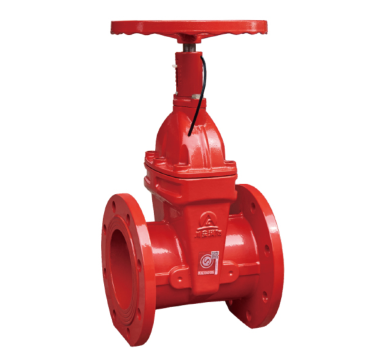
[IMAGE: gate valve with tamper switch installed on fire sprinkler riser — CA-FIRE flanged type] [IMAGE ALT TEXT: gate valve with tamper switch installed fire sprinkler riser — CA-FIRE flanged ZSXZF4]
Fire Sprinkler System Risers and Zone Control
The most common application for a gate valve with tamper switch is as the primary zone control valve on wet-pipe, dry-pipe and pre-action automatic sprinkler system risers. Positioned upstream of the alarm valve or flow switch, it provides the code-required supervisory monitoring to ensure the sprinkler system water supply cannot be interrupted without triggering an immediate alarm at the FACP. This is a mandatory requirement under NFPA 13 for all sprinkler system control valves.
Fire Hydrant and Standpipe Supply Mains
Installed as a supply isolation valve on fire hydrant branch connections and standpipe supply risers, the flanged gate valve with tamper switch enables building operators and fire departments to remotely confirm that hydrant supply valves are fully open and ready for use — without physically visiting each valve location. Any unauthorized valve operation during routine building works or maintenance activities triggers an immediate supervisory alarm.
Sprinkler System Sectional Isolation
Used as sectional isolation valves between sprinkler system zones in large buildings, shopping centres and multi-floor commercial complexes. When any section must be taken out of service for maintenance or modification, the tamper switch on the gate valve immediately notifies the FACP that the section is isolated — ensuring the building’s fire safety management team can implement appropriate compensatory measures such as fire watch patrols.
Building Plant Rooms and Riser Enclosures
The compact non-rising stem profile of this gate valve with tamper switch makes it well suited to above-ground installations in plant rooms, riser enclosures and valve cupboards where space is restricted. The flanged connection ensures a permanent, stable joint that does not require periodic retightening, reducing maintenance demands in locations that may only be accessed during scheduled inspections.
Industrial and High-Risk Facilities
Petrochemical plants, warehouses storing flammable materials and other high-risk industrial facilities often require additional certainty that fire protection control valves are maintained in the correct open position at all times. The continuous supervisory monitoring provided by a gate valve with tamper switch — feeding directly into the site’s fire alarm or process safety system — meets this requirement reliably and cost-effectively.
How the Tamper Switch Works
Understanding the tamper switch operation helps engineers and contractors specify and commission the gate valve with tamper switch correctly.
Under normal operation, the gate valve is maintained in the fully open position. The tamper switch contacts are in their resting (non-alarm) state, and no signal is sent to the FACP. When the handwheel is turned and the valve begins to close, the switch actuator — linked mechanically to the valve stem — begins to move. At the point where the valve has closed approximately 20% of its full travel, the switch contacts change state and a supervisory signal is transmitted to the FACP over the DC 24V supervisory circuit.
The FACP registers this as a supervisory condition — distinct from a fire alarm — and alerts the operator. When the valve is returned to the fully open position, the switch contacts reset and the FACP registers a supervisory restoral. This entire sequence — from valve movement to FACP signal — occurs in under 0.5 seconds, ensuring operators receive near-instantaneous notification of any valve operation.
Installation Guidelines
Pre-Installation Checklist
- Verify the gate valve with tamper switch nominal diameter and pressure rating match the pipeline specification.
- Confirm the tamper switch output voltage (DC 24V) and contact rating (0.5A) are compatible with the connected FACP supervisory input circuit.
- Check that the valve body, tamper switch housing and flanged faces are free of transit damage.
- Ensure the pipeline is thoroughly flushed before installing the valve to prevent debris from damaging the resilient wedge or seat surfaces.
Flanged Connection Installation
Orient the gate valve with tamper switch so the flow direction arrow on the body aligns with the pipeline flow direction. Place the correct gasket material between the valve and pipeline flanges, then tighten all bolts evenly in a cross pattern to the manufacturer’s torque specification. Confirm the tamper switch housing is positioned for clear visual inspection and unobstructed access to the signal wiring terminals.
Signal Wiring
Connect the tamper switch signal wires to the designated supervisory input zone on the fire alarm control panel, following both the FACP manufacturer’s wiring diagram and the valve manufacturer’s connection instructions. Route all signal cabling in a metallic conduit to protect against mechanical damage. After wiring, test the complete supervisory circuit by partially closing the gate valve with tamper switch and confirming the FACP registers a supervisory alarm, then restore the valve to full open and confirm the FACP registers a restoral.
Post-Installation Testing
- Conduct a hydrostatic pressure test to 3.2 MPa — hold for the required duration and check for leaks at the body, flanges and tamper switch housing penetrations.
- Fully open and close the valve to verify smooth operation and correct dial indicator readings.
- Perform a complete tamper switch functional test — close the valve to the trigger point and verify FACP alarm, then restore and verify FACP restoral.
- Lock the valve in the fully open position with a padlock or tamper-seal and attach a valve identification tag.
- Document installation date, test results and commissioning engineer’s details in the fire protection system logbook.
Maintenance Schedule
Maintenance must comply with NFPA 25 (Inspection, Testing and Maintenance of Water-Based Fire Protection Systems) and applicable local fire protection standards.
Monthly — Visual Inspection
- Confirm the gate valve with tamper switch dial indicator shows fully open position.
- Verify the valve is locked or tamper-sealed in the open position.
- Check the FACP supervisory zone for this valve shows a normal (non-alarm) status.
- Inspect the valve body, flanges and tamper switch housing for leaks, corrosion or mechanical damage.
Quarterly — Functional Test
- Partially close the valve to verify the tamper switch triggers a supervisory alarm at the FACP at the correct point.
- Restore the valve to full open and confirm the FACP supervisory restoral signal is received.
- Check and tighten any loose flange bolts.
- Inspect signal wiring conduit for damage.
Annual — Full Inspection
- Disassemble the bonnet and inspect the stem, stem nut, resilient wedge and sealing components for wear or deterioration.
- Conduct a full pressure and seal test to 3.2 MPa and record results.
- Test and calibrate the tamper switch trigger point — replace the switch module if response time exceeds 0.5 seconds or trigger point has drifted outside specification.
- Replace packing and sealing components preventively — recommended every 2 years.
- Clean the tamper switch housing contact points and inspect wiring insulation for aging or cracking.
Gate Valve with Tamper Switch — Frequently Asked Questions
What is a gate valve with tamper switch used for?
A gate valve with tamper switch is used as a supervised control valve in fire protection systems — specifically on automatic sprinkler system risers, fire hydrant supply mains and standpipe systems. It provides two functions simultaneously: on/off isolation of the fire water supply, and continuous electronic monitoring of the valve’s open/closed position. Any movement of the valve from fully open triggers an immediate supervisory signal to the fire alarm control panel, satisfying the supervisory valve monitoring requirements of NFPA 13.
How is a gate valve with tamper switch different from a standard signal gate valve?
Both products serve similar supervisory functions, but they differ in their primary design orientation. The standard signal gate valve (such as the CA-FIRE ZSXZF4-Q-50~300-16 with grooved connection) is optimised for compact installation with grooved end connections and is often specified where fast installation and flexibility of connection are priorities. The flanged gate valve with tamper switch is optimised for permanent, high-integrity flanged pipeline connections and is preferred for main riser and primary system applications where connection robustness and long-term reliability are the overriding design criteria.
At what point does the tamper switch trigger?
The tamper switch on CA-FIRE’s flanged gate valve with tamper switch is factory-calibrated to trigger when the valve has closed approximately 20% of its full travel from the fully open position. This early-warning trigger point ensures the supervisory alarm is generated well before the valve closure is sufficient to meaningfully reduce water flow to the fire suppression system — giving building operators maximum time to identify and correct the issue.
Is the DC 24V output compatible with all fire alarm control panels?
The DC 24V / 0.5A dry contact output of the gate valve with tamper switch is compatible with the supervisory input circuits of virtually all modern fire alarm control panels manufactured to EN 54, UL 864, AS 4428 and equivalent standards. Confirm the specific FACP’s supervisory circuit input voltage and contact rating requirements with the FACP manufacturer before wiring.
What is the difference between a flanged and grooved gate valve with tamper switch?
The flanged gate valve with tamper switch uses bolted flange joints — permanent connections that provide maximum joint integrity and are preferred for main risers and primary system applications. The grooved (Victaulic-compatible) version uses mechanical couplings that can be assembled and disassembled without cutting the pipe, offering faster installation and easier future access for maintenance or system modification. Both are electrically and functionally identical — the choice between them is driven by pipeline design, installation speed requirements and maintenance access considerations.
Why Specify CA-FIRE’s Gate Valve with Tamper Switch?
CA-FIRE specialises exclusively in fire protection equipment, bringing focused engineering expertise to every product in our range. Each gate valve with tamper switch undergoes factory testing that includes hydrostatic pressure verification to 6.4 MPa, seal integrity confirmation at 3.2 MPa, tamper switch trigger point calibration and signal response time measurement. Only valves that meet every specification leave our production facility.
With a manufacturing base certified to ISO 9001 and products certified to GB 15930 and CE standards, CA-FIRE’s gate valve with tamper switch is accepted by fire authorities and system designers across more than 50 countries. Our technical team provides full support from specification assistance through to commissioning and maintenance training — ensuring your fire protection system performs as designed when it matters most.
Get a Quote
Contact CA-FIRE for pricing, technical drawings, project specifications or OEM enquiries. Our engineering team responds within one business day.
- Email: sales@ca-fire.com
- Mobile / WhatsApp: +86 13400715622
- WeChat: 404863577
- Website: www.ca-fire.com
Related products: Signal Gate Valve — Grooved Type · OS&Y Gate Valve · NRS Gate Valve · Gate Valve Series · Fire Alarm Valves
For supervisory valve monitoring requirements, refer to NFPA 13 and NFPA 25.
| Parameter | Specification |
|---|---|
| Product Model | ZSXZF4-Q-50~300-16 |
| Valve Type | Gate Valve with Tamper Switch — Flanged, Non-Rising Stem |
| Nominal Pressure | 1.6 MPa (PN16) |
| Nominal Diameter | DN50–DN300 |
| Strength Test Pressure | 6.4 MPa |
| Seal Test Pressure | 3.2 MPa |
| Applicable Medium | Water, foam fire suppression mixture |
| Medium Temperature | 4–70 °C |
| Switch Contact Capacity | DC 24V / 0.5A |
| Signal Trigger Point | Valve closure reaches 20% of full travel |
| Signal Transmission Delay | < 0.5 seconds |
| Connection Method | Flanged (ANSI B16.1 / DIN 2501 PN16) |
| Stem Design | Non-Rising Stem (NRS) with dial position indicator |
| Certifications | GB 15930, ISO 9001, CE |
| Nominal Diameter | Structural Length (mm) |
|---|---|
| DN50 | 185 |
| DN65 | 190 |
| DN80 | 200 |
| DN100 | 228 |
| DN125 | 255 |
| DN150 | 270 |
| DN200 | 290 |
| DN250 | 330 |
| DN300 | 358 |