
NRS Gate Valve for Fire Protection Systems — Non-Rising Stem Design
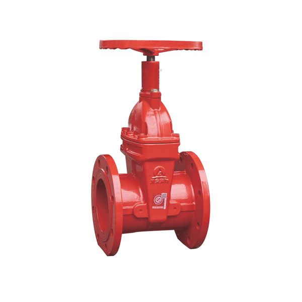
The NRS gate valve, or Non-Rising Stem gate valve, is a compact indicating gate valve engineered for fire protection pipelines where installation space is limited. Unlike a rising stem OS&Y valve, the stem of an NRS gate valve rotates in place without extending above the bonnet — keeping the overall installed height constant regardless of valve position. A built-in dial indicator on the bonnet shows the open/close degree at a glance, providing the position indication required by NFPA 13 for fire protection control valves.
CA-FIRE’s NRS gate valve (Model: ZSZF4-Q-50~400-16) is the preferred choice for underground valve pits, basement plant rooms, valve chambers and any installation where overhead clearance is restricted. Available in DN50–DN400 with flanged and grooved end connections, it is trusted by fire protection engineers and contractors across more than 50 countries.
NRS Gate Valve Technical Specifications
| Parameter | Specification |
|---|---|
| Product Model | ZSZF4-Q-50~400-16 |
| Valve Type | NRS Gate Valve (Non-Rising Stem) |
| Nominal Pressure | 1.6 MPa (PN16) |
| Nominal Diameter | DN50–DN400 |
| Strength Test Pressure | 6.4 MPa |
| Seal Test Pressure | 3.2 MPa |
| Applicable Medium | Water, foam fire suppression mixture |
| Medium Temperature | 4–70 °C |
| Connection Method | Flanged (ANSI B16.1 / DIN 2501) / Grooved (Victaulic-compatible) |
| Stem Design | Non-Rising Stem (NRS) — stem rotates in place |
| Position Indicator | Built-in dial indicator showing open/close degree |
| Wedge Type | Resilient wedge, rubber-encapsulated |
| Certifications | GB 12736, ISO 9001, CE |
Structural Length by Nominal Diameter
| Nominal Diameter | Flange Type (mm) | Grooved Type (mm) |
|---|---|---|
| DN50 | 185 | 150 |
| DN65 | 190 | 160 |
| DN80 | 200 | 175 |
| DN100 | 228 | 185 |
| DN125 | 255 | 205 |
| DN150 | 270 | 212 |
| DN200 | 290 | 248 |
| DN250 | 330 | 263 |
| DN300 | 358 | — |
| DN350 | 377 | — |
| DN400 | 405 | — |
NRS Gate Valve Key Features
Compact Non-Rising Stem — Space-Saving Installation
The core advantage of the NRS gate valve is its fixed overall height. Because the stem does not travel upward when the valve opens, no overhead clearance is required beyond the valve’s own bonnet height. This makes the NRS gate valve the standard choice for underground valve pits, below-ground valve chambers, basement plant rooms and any confined mechanical space where an OS&Y gate valve’s rising stem would be impractical or impossible to accommodate.
Built-In Dial Position Indicator
Since the stem of an NRS gate valve does not rise visibly, a clearly marked dial indicator is fitted to the bonnet to show the valve’s open/close position at all times. The indicator displays the degree of opening, allowing operators to confirm valve status during inspections without operating the valve. This indicator satisfies NFPA 13’s requirement for indicating-type control valves in fire protection systems.
Resilient Wedge for Reliable Sealing
The rubber-encapsulated resilient wedge delivers a tight, bi-directional seal against the valve seats, ensuring zero leakage when fully closed. The elastomeric coating compensates for minor seat irregularities and thermal expansion, maintaining sealing integrity across the full 4–70°C operating temperature range. Unlike older solid metal wedge designs, the resilient wedge eliminates hydraulic lock risk and ensures consistently low operating torque throughout the valve’s service life.
Full-Bore Flow Path — Minimal Pressure Drop
When fully open, the NRS gate valve presents an unobstructed, full-bore flow path through the body, producing negligible pressure drop. This is essential in fire suppression system hydraulic design — maintaining adequate residual pressure and flow rate at every sprinkler head and hose connection throughout the system.
Dual Connection Options — Flanged and Grooved
Both flanged (ANSI B16.1 / DIN 2501 PN16) and grooved (Victaulic-compatible) end connections are available across the full DN50–DN400 size range. The grooved connection option significantly reduces installation time compared to flanged joints, making the NRS gate valve a popular choice for fast-track fire protection projects and retrofit installations.
NRS Gate Valve Applications
[IMAGE: NRS gate valve installed in underground valve pit fire protection — CA-FIRE] [IMAGE ALT TEXT: NRS gate valve installed underground valve pit fire protection — CA-FIRE non-rising stem]
Underground and Buried Fire Mains
The NRS gate valve is the standard sectional isolation valve on underground fire water mains, yard mains and below-ground fire hydrant branch connections. Its fixed height profile fits cleanly inside standard valve boxes and pits, and its non-rising stem eliminates the risk of stem damage from backfill or ground movement. The flanged or grooved connections provide a secure, leak-free joint in buried service.
Basement and Confined Plant Rooms
In basement fire pump rooms, mechanical plant rooms and other confined spaces with low ceiling heights, the NRS gate valve is preferred over the OS&Y design. The absence of a rising stem means the valve can be installed in locations where vertical clearance above the pipeline is insufficient for a rising stem valve to fully open.
Fire Sprinkler System Control Valves
Installed as zone control valves and floor isolation valves on wet-pipe, dry-pipe and pre-action sprinkler systems. The NRS gate valve’s dial position indicator satisfies NFPA 13’s indicating valve requirement, while its compact profile makes it suitable for riser cupboards and ceiling-void installations where space is at a premium.
Fire Hydrant Systems
Used as a supply control valve on fire hydrant branch connections and hydrant supply mains, particularly in locations where the valve must be installed in a below-ground pit or surface box. The NRS gate valve’s low profile and non-rising stem make it the most practical choice for these applications.
Industrial Facilities and Petrochemical Plants
In industrial environments where fire water pipelines run through congested pipe racks, underground trenches or confined process areas, the NRS gate valve provides reliable on/off isolation without the spatial demands of a rising stem valve. The epoxy-coated ductile iron body resists corrosion in wet and chemically aggressive environments.
NRS Gate Valve vs. OS&Y Gate Valve — Which to Specify?
| NRS Gate Valve (Non-Rising Stem) | OS&Y Gate Valve (Rising Stem) | |
|---|---|---|
| Overhead clearance needed | Minimal — stem stays in place | Required — stem rises full travel |
| Visual position indication | Dial indicator on bonnet | Rising stem — visible at a glance |
| NFPA 13 indicating valve | ✓ Yes (with dial indicator) | ✓ Yes |
| Underground / pit-mounted | ✓ Preferred | Less suitable |
| Above-ground accessible | Suitable | Preferred |
| Grooved end available | ✓ Yes | Optional |
| Supervisory tamper switch | Optional add-on | Optional add-on |
General rule: Specify the NRS gate valve for underground, confined or space-restricted installations. Specify the OS&Y gate valve for above-ground, accessible locations where direct visual stem indication is required or preferred by the authority having jurisdiction.
Installation Guidelines
Pre-Installation Checklist
- Verify the NRS gate valve nominal diameter, pressure rating and connection type (flanged or grooved) match the pipeline specification.
- Confirm that the dial indicator is clearly visible from the intended inspection position after installation.
- Inspect the valve body, wedge, stem and connection faces for transit damage before installation.
- Ensure the pipeline is flushed and free of debris prior to valve installation.
Flanged Connection Installation
Align the NRS gate valve body with the flow direction arrow matching the pipeline flow direction. Insert the correct gasket material between flanges and tighten all bolts evenly in a cross pattern to the manufacturer’s specified torque — uneven torque is the most common cause of flange joint leakage. For underground installations, verify that the valve is correctly bedded and supported to prevent pipe load being transferred to the valve body.
Grooved Connection Installation
Clean the pipe groove and valve groove interface thoroughly. Position the gasket centrally over the joint and fit the grooved coupling housing, tightening the coupling bolts evenly until the housing pads make firm metal-to-metal contact. Do not over-torque, as this can deform the gasket and compromise the seal.
Post-Installation Testing
- Pressure test to 3.2 MPa (seal test) — hold for the required duration and confirm no leakage at body, connection joints or stem packing.
- Fully open and fully close the NRS gate valve to confirm smooth, jam-free operation throughout full travel.
- Confirm the dial indicator correctly displays fully open and fully closed positions.
- Lock the valve in the fully open position and attach a valve identification tag.
- Record installation date, test pressures, results and inspector’s name in the fire protection system logbook.
Maintenance Schedule
Maintenance of the NRS gate valve must comply with NFPA 25 (Inspection, Testing and Maintenance of Water-Based Fire Protection Systems) and applicable local standards.
Monthly — Visual Inspection
- Confirm the NRS gate valve dial indicator shows the fully open position.
- Check that the valve is locked or tamper-sealed in the open position.
- Inspect the valve body and connection joints for leaks, corrosion or physical damage.
- Check stem packing area for signs of weeping or leakage.
Quarterly — Operational Test
- Operate the NRS gate valve through its full travel — confirm smooth, jam-free opening and closing with no unusual resistance.
- Verify the dial indicator accurately reflects valve position at both full open and full closed.
- Check and tighten any loose flange bolts or grooved coupling fasteners.
Annual — Full Inspection
- Disassemble and inspect the stem, stem nut, packing and resilient wedge for wear, corrosion or deterioration.
- Conduct a full pressure and seal test (3.2 MPa) and record results.
- Replace packing and sealing components as required — recommended every 2 years as a preventive measure.
- Lubricate the stem threads and stem nut with a water-resistant, fire-system approved grease.
- Calibrate and verify the dial indicator accuracy.
NRS Gate Valve — Frequently Asked Questions
What does NRS stand for in a gate valve?
NRS stands for Non-Rising Stem. In an NRS gate valve, the stem rotates in place within the bonnet to open and close the valve gate — unlike an OS&Y (rising stem) gate valve, where the stem travels upward as the valve opens. Because the stem does not extend above the bonnet, the NRS gate valve maintains a fixed installed height regardless of valve position, making it the preferred design for confined and underground installations.
Is an NRS gate valve NFPA 13 compliant for fire protection?
Yes. NFPA 13 requires fire protection control valves to be of an indicating type — the valve’s open or closed status must be determinable without operating the valve. The NRS gate valve satisfies this requirement through its built-in bonnet dial indicator, which displays the valve’s open/close position at all times. When combined with a supervisory tamper switch for electronic monitoring, the NRS gate valve fully meets the supervisory requirements of NFPA 13 for sprinkler system control valves.
What is the difference between an NRS gate valve and an OS&Y gate valve?
The key difference is stem behaviour. In an NRS gate valve, the stem stays at a fixed height and rotates internally — there is no visual stem movement to confirm position, so a dial indicator is used. In an OS&Y gate valve, the stem visibly rises above the handwheel when the valve opens, providing direct visual confirmation of valve status from a distance. The NRS gate valve is preferred where overhead space is limited; the OS&Y gate valve is preferred where direct visual stem indication is required or mandated by code.
Can an NRS gate valve be fitted with a supervisory tamper switch?
Yes. A supervisory tamper switch can be added to the NRS gate valve to provide electronic monitoring of valve position, sending a signal to the fire alarm control panel if the valve is moved from the fully open position. This is the function provided by CA-FIRE’s signal gate valve (ZSXZF4-Q-50-300-16), which combines the space-saving non-rising stem design with built-in tamper switch signal feedback. If both space efficiency and electronic supervisory monitoring are required, the signal gate valve model is the correct specification.
What sizes are available for the CA-FIRE NRS gate valve?
CA-FIRE’s NRS gate valve is available from DN50 to DN400, with flanged end connections per ANSI B16.1 or DIN 2501, and grooved end connections (Victaulic-compatible) available in DN50–DN250. This covers the full range of standard fire protection pipeline sizes encountered in building services, industrial and infrastructure projects.
Why Specify CA-FIRE’s NRS Gate Valve?
CA-FIRE is a dedicated fire protection equipment manufacturer with integrated R&D, production, quality control and after-sales support. Every NRS gate valve leaving our facility has passed:
- Hydrostatic pressure testing to 6.4 MPa (4× working pressure)
- Seal integrity testing to 3.2 MPa
- Full dimensional inspection against GB 12736 and customer-specified standards
- Dial indicator accuracy verification across the full DN50–DN400 size range
CA-FIRE’s NRS gate valve is available in DN50–DN400, with flanged and grooved connection options, full compliance with NFPA 13 and GB 12736, and optional supervisory tamper switch for integrated fire alarm panel monitoring. Our products are installed across more than 50 countries in high-rise buildings, industrial facilities, underground infrastructure and public projects. Custom specifications and OEM supply are available — contact our engineering team for project-specific requirements.
Get a Quote
Contact CA-FIRE for pricing, technical drawings, project specifications or OEM enquiries. Our engineering team responds within one business day.
- Email: sales@ca-fire.com
- Mobile / WhatsApp: +86 13400715622
- WeChat: 404863577
- Website: www.ca-fire.com
Related products: Signal Gate Valve · OS&Y Gate Valve · Gate Valve Series · Fire Alarm Valves
For NRS gate valve inspection and testing requirements, refer to NFPA 25.
| Parameter | Specification |
|---|---|
| Product Model | ZSZF4-Q-50~400-16 |
| Valve Type | NRS Gate Valve (Non-Rising Stem) |
| Nominal Pressure | 1.6 MPa (PN16) |
| Nominal Diameter | DN50–DN400 |
| Strength Test Pressure | 6.4 MPa |
| Seal Test Pressure | 3.2 MPa |
| Applicable Medium | Water, foam fire suppression mixture |
| Medium Temperature | 4–70 °C |
| Connection Method | Flanged (ANSI B16.1 / DIN 2501) / Grooved (Victaulic-compatible) |
| Stem Design | Non-Rising Stem (NRS) — stem rotates in place |
| Position Indicator | Built-in dial indicator showing open/close degree |
| Wedge Type | Resilient wedge, rubber-encapsulated |
| Certifications | GB 12736, ISO 9001, CE |
| Nominal Diameter | Flange Type (mm) | Grooved Type (mm) |
|---|---|---|
| DN50 | 185 | 150 |
| DN65 | 190 | 160 |
| DN80 | 200 | 175 |
| DN100 | 228 | 185 |
| DN125 | 255 | 205 |
| DN150 | 270 | 212 |
| DN200 | 290 | 248 |
| DN250 | 330 | 263 |
| DN300 | 358 | — |
| DN350 | 377 | — |
| DN400 | 405 | — |