
Pre Action Alarm Valve — ZSFY Series Double-Interlock Sprinkler Protection
A pre action alarm valve is the control component in a pre-action sprinkler system that holds water back from the distribution pipework until two independent events confirm a genuine fire — a signal from the fire detection system and physical activation of a sprinkler head. This double-interlock mechanism makes it the most selective automatic sprinkler control valve available, and the standard specification wherever accidental water discharge would be as damaging as the fire it suppresses: data centres, server rooms, archives, museums, cold stores and hazardous industrial facilities.
CA-FIRE’s ZSFY Series pre action alarm valve is available in four configurations — standard flanged, grooved-end, stainless steel and explosion-proof — covering DN80 through DN250 across the full range of commercial, industrial and specialist applications. Every unit is factory-tested to GB 5135.2-2019 and designed in compliance with NFPA 13, UL 312 and FM 1120, with Ministry of Public Security fire product type approval certification.
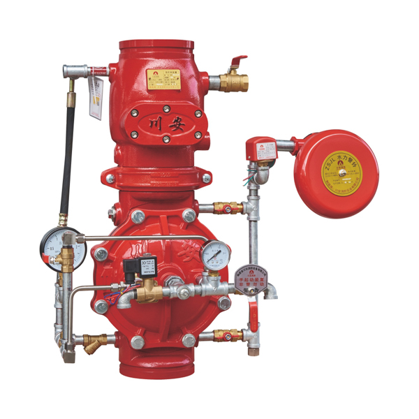
Pre Action Alarm Valve — Four ZSFY Series Configurations
[IMAGE: pre action alarm valve ZSFY series four types flanged grooved stainless steel explosion proof — CA-FIRE] [IMAGE ALT TEXT: pre action alarm valve ZSFY series four configurations — CA-FIRE flanged grooved stainless explosion-proof]
Type 1 — Standard Flanged Pre Action Alarm Valve
The widest size range in the ZSFY series — DN80 through DN250 — making it the standard specification for commercial office towers, mixed-use developments, high-rise residential buildings and institutional facilities where pre-action protection is required for water-sensitive zones. Flanged connections per ANSI B16.1 or DIN 2501 interface directly with standard pipeline flanges. The integrated IP65 control panel provides local status indication, electrical activation input from the fire detection system, manual override capability and pressure switch outputs for fire alarm panel connection. Compatible with both electrical activation and wet or dry pilot line activation modes.
Type 2 — Grooved Pre Action Alarm Valve (ZSFY-1.6G)
Grooved Victaulic IPS-compatible end connections replace flange bolt work with mechanical couplings — reducing installation time at the alarm valve station by more than 50% compared to the flanged equivalent. The preferred specification for fast-track construction programmes, phased fit-outs in occupied buildings and retrofit upgrades to existing grooved sprinkler systems. Available in DN100, DN150 and DN200. Ductile iron QT450-10 body with epoxy powder coating. IP65 control panel, DC 24V/0.5A pressure switch output.
Type 3 — Stainless Steel Pre Action Alarm Valve (ZSFY-1.6P-Ex)
316L stainless steel body for installations in corrosive, high-humidity or chemically aggressive environments — offshore platforms, coastal industrial plants, pharmaceutical cleanrooms, wastewater treatment facilities and food processing buildings where ductile iron would corrode within its design service life. The Ex-certified variant is additionally qualified for Zone 1 and Zone 2 explosive atmosphere classified locations (Ex db IIBT6Gb / Ex tb IIIC T80°C Db), making it the correct pre action alarm valve specification for petrochemical storage, paint spray booths and solvent processing areas. Available in DN100, DN150 and DN200.
Type 4 — Explosion-Proof Pre Action Alarm Valve with Linkage Control Panel
A self-contained Ex-certified solution for classified hazardous locations requiring both the double-interlock protection of a pre action alarm valve and full Ex-rated electrical control. The integrated linkage control panel — certified to Ex db IIBT6Gb / Ex tb IIIC T80°C Db, IP65 — manages the complete activation sequence: receiving detector signals, commanding the solenoid release valve, monitoring supervisory air pressure and logging alarm events, all within a single Ex-rated enclosure. Eliminates the need for separate Ex junction boxes and minimises field wiring complexity in hazardous area installations. Available in DN100, DN150 and DN200.
Technical Specifications
Stainless Steel Flanged and Grooved Models
| Parameter | SS Flanged (ZSFY-1.6P-Ex) | Grooved (ZSFY-1.6G) |
|---|---|---|
| Nominal Diameters | DN100 / DN150 / DN200 | DN100 / DN150 / DN200 |
| Height — DN100 (mm) | 600 | 610 |
| Height — DN150 (mm) | 740 | 730 |
| Height — DN200 (mm) | 930 | 865 |
| Working Pressure | 1.6 MPa | 1.6 MPa |
| Seal Test Pressure | 3.2 MPa | 3.2 MPa |
| Strength Test Pressure | 6.4 MPa | 6.4 MPa |
| Supervisory Air Pressure | 0.03–0.05 MPa | 0.03–0.05 MPa |
| Body Material | 316L Stainless steel | Ductile iron QT450-10 |
| Surface Treatment | Electro-polished | Epoxy powder coated |
| Connection | Flanged ANSI/DIN | Grooved — Victaulic IPS |
| Control Modes | Electrical / Wet or Dry Pilot / Manual | Electrical / Wet or Dry Pilot / Manual |
| Medium | Water, foam-water mixture | Water, foam-water mixture |
| Temperature Range | 4–70 °C | 4–70 °C |
| Control Panel Protection | IP65 | IP65 |
| Ex Certification | Ex db IIBT6Gb / Ex tb IIIC T80°C Db | — |
| Pressure Switch Output | DC 24V / 0.5A | DC 24V / 0.5A |
Standard Flanged Model (All Sizes)
| Parameter | Specification |
|---|---|
| Nominal Diameters | DN80 / DN100 / DN150 / DN200 / DN250 |
| Working Pressure | 1.6 MPa |
| Seal Test Pressure | 3.2 MPa |
| Strength Test Pressure | 6.4 MPa |
| Supervisory Air Pressure | 0.03–0.05 MPa |
| Body Material | Ductile iron, epoxy coated |
| Connection | Flanged — ANSI B16.1 / DIN 2501 |
| Control Modes | Electrical / Wet or Dry Pilot / Manual |
| Medium | Water, foam-water mixture |
| Temperature Range | 4–70 °C |
| Control Panel Protection | IP65 |
| Pressure Switch Output | DC 24V / 0.5A |
| Standard | GB 5135.2-2019, NFPA 13 |
How the Pre Action Alarm Valve Works
The operating cycle of the ZSFY pre action alarm valve has five distinct stages, each of which can be independently verified during commissioning and maintenance testing.
Stage 1 — Supervised standby. The pre action alarm valve is closed. The supply side carries full system water pressure. The distribution pipework on the system side is charged with compressed air at supervisory pressure (0.03–0.05 MPa). A pressure switch monitors this supervisory air continuously — if it drops below setpoint due to a pipeline leak or break, the fire alarm panel receives a trouble signal, alerting maintenance personnel to investigate before any water enters the system.
Stage 2 — Fire detection triggers pre-trip. When smoke, heat or multi-sensor detectors in the protected zone signal a confirmed fire event, the fire alarm control panel sends an electrical command to the pre action alarm valve control panel. The panel activates the solenoid release valve, venting the actuating chamber and tripping the main clapper open. Water floods the distribution pipework. No water can yet escape — all sprinkler heads remain sealed.
Stage 3 — Sprinkler head activation releases water. As the fire grows and temperature at the nearest sprinkler head reaches its rated activation threshold (typically 68°C or 79°C), the thermosensitive glass bulb shatters. Because the pre action alarm valve has already opened, the distribution pipework is full of water and the activated head delivers immediate full-flow discharge — identical in response speed to a wet pipe system.
Stage 4 — Dual alarm activation. The moment the pre action alarm valve trips in Stage 2, the alarm port pressure change activates both the water motor alarm gong (mechanical audible alarm — no electrical power required) and the pressure switch (electronic signal to the fire alarm control panel). On-site occupants hear the gong; the fire control room receives a simultaneous alarm signal. Human response is initiated well before water is discharged.
Stage 5 — Reset. After extinguishment: close the supply isolation valve, drain the system side, replace operated sprinkler heads, manually reset the pre action alarm valve clapper, restore supervisory air pressure, then slowly reopen the supply valve to return to supervised standby. The complete reset can be performed by trained facility maintenance staff using the CA-FIRE installation manual provided with every valve.
Pre Action vs. Wet vs. Dry Alarm Valve — Selection Guide
| Pre Action Alarm Valve | Wet Alarm Valve | Dry Alarm Valve | |
|---|---|---|---|
| Downstream pipework | Supervisory air | Water | Air / nitrogen |
| Activation requirement | Detection signal + sprinkler head | Sprinkler head only | Sprinkler head only |
| False discharge protection | ✓ Maximum — dual interlock | Low | Low |
| Response speed once tripped | ✓ Immediate — pipe pre-filled | ✓ Immediate | Slower — air must vent |
| Freezing environment suitability | ✓ Yes | No | ✓ Yes |
| System complexity | Most complex | ✓ Simplest | Moderate |
| Best application | Data centres, archives, cold stores, hazardous areas | Standard occupied buildings | Unheated spaces |
Specify the pre action alarm valve when accidental water discharge would cause unacceptable damage, when the environment is subject to freezing, or when hazardous area classification requires Ex-certified components. Specify the wet alarm valve for standard occupied buildings above 4°C. Specify the dry alarm valve for unheated spaces where freezing is the only concern and false discharge risk is acceptable.
Applications
[IMAGE: pre action alarm valve installed data centre server room fire protection — CA-FIRE ZSFY] [IMAGE ALT TEXT: pre action alarm valve installed data centre fire protection system — CA-FIRE ZSFY series]
Data Centres and Server Rooms
IT infrastructure losses from a single inadvertent sprinkler discharge can far exceed the value of fire damage the system was designed to prevent. NFPA 75 (Standard for the Fire Protection of Information Technology Equipment) recognises the pre action alarm valve as the preferred automatic sprinkler control for IT equipment rooms. The double-interlock design means a physically damaged sprinkler head cannot release water without an accompanying confirmed detection signal — providing the protection level that major cloud providers, co-location operators and enterprise data centre owners require. CA-FIRE’s ZSFY flanged model with integrated IP65 control panel, wired to VESDA or addressable detection, is the standard configuration for this application.
Archives, Museums and Libraries
Water damage to irreplaceable documents, artworks and cultural artefacts is unrecoverable. The pre action alarm valve provides the highest accidental-discharge protection available within a water-based suppression system. In confirmed fire events, the dual-event activation still delivers water quickly enough to suppress fires before flashover — satisfying both conservation requirements and fire insurer specifications. The stainless steel ZSFY-1.6P-Ex variant is specified for naturally humidified archive and museum environments where ductile iron would corrode over the system’s design service life.
Cold Storage and Blast-Freezer Facilities
Wet sprinkler systems are not viable below 4°C — standing water in distribution pipework freezes and bursts the pipe. The pre action alarm valve’s dry supervisory configuration eliminates freeze risk entirely. Using a dry pilot line activation mode rather than electrical detection avoids any water-filled component within the cold zone, enabling reliable fire protection in environments as cold as −30°C. CA-FIRE’s ZSFY grooved model is frequently specified for cold chain logistics facilities, blast-freezer warehouses and refrigerated distribution centres.
Pharmaceutical Cleanrooms and Electronics Manufacturing
Cleanroom environments require contamination control alongside fire protection. The pre action alarm valve’s dry standby state means no water is present in distribution pipework within the cleanroom during normal operation — eliminating condensation and corrosion-related water quality risks. The stainless steel body variant is compatible with GMP pharmaceutical facility requirements for stainless distribution pipework and provides a clean, electropolished surface that does not harbour bacterial growth.
Petrochemical Plants and Hazardous Area Facilities
Zone 1 and Zone 2 classified locations in petrochemical storage, solvent processing and spray-finishing facilities require Ex-certified fire protection components. CA-FIRE’s explosion-proof ZSFY pre action alarm valve (Ex db IIBT6Gb / Ex tb IIIC T80°C Db) provides fully compliant fire suppression control in the most demanding hazardous area classifications. Compatibility with foam-water mixture allows integration with foam-water deluge systems for enhanced flammable liquid suppression.
Mixed-Use High-Rise Buildings
High-rise commercial and residential buildings often contain both standard occupancies and water-sensitive zones — server closets, archival storage, electrical switchrooms — within the same riser system. A pre action alarm valve on the branches serving sensitive zones provides targeted double-interlock protection without requiring a completely separate suppression system type for those areas.
Installation Guidelines
Pre-Installation Checklist
- Confirm the pre action alarm valve nominal diameter and pressure rating match the hydraulic design drawings.
- Verify adequate clearance above and to all sides of the valve body for control panel access, trim piping, pressure gauges and annual maintenance — minimum 800 mm recommended on all sides.
- Confirm fire detection zone wiring is routed to the valve control panel with the correct cable specification and segregation from power cables.
- Arrange a clean, dry compressed air or nitrogen supply for supervisory pressure — pressure regulator and isolation valve required upstream of the supervisory connection.
Mechanical Installation
Install the pre action alarm valve vertically with water flowing upward through the clapper. For grooved models, ensure pipe end cuts are square and rolled grooves conform to the Victaulic IPS coupling manufacturer’s dimensional specification. For flanged models, use full-face gaskets and tighten flange bolts in a cross-pattern sequence to the torque values in the CA-FIRE installation manual.
Connect the supervisory air supply to the distribution side before commissioning the fire detection system wiring — establishing supervisory pressure first identifies any pipeline leaks before the detection system is live and capable of tripping the valve.
Commissioning Sequence
Use the integrated test valve to conduct a controlled partial trip without flooding the full distribution network. Verify: alarm gong activates within the NFPA 13 specified time; pressure switch signal reaches the fire alarm control panel; supervisory air pressure restores to setpoint after the test drain valve closes; and the pre action alarm valve resets without residual clapper leakage. Document all commissioning results for authority inspection submission.
Maintenance Schedule
Per NFPA 25 requirements for pre-action sprinkler systems:
| Frequency | Task |
|---|---|
| Weekly | Visual inspection — supervisory air pressure gauge, supply pressure gauge, valve exterior and trim for leaks or damage |
| Monthly | Confirm upstream isolation valve is fully open and in supervised position; check control panel for fault indicators |
| Quarterly | Partial trip test via inspector’s test valve — verify alarm gong and pressure switch response; check supervisory air restoration time |
| Annually | Full trip test — open inspector’s test connection fully, verify complete activation sequence, inspect clapper and seat internally after draining |
| Every 5 years | Full internal body inspection, replace NBR sealing elements, recalibrate control panel, replace supervisory air pressure switch if drift detected |
Frequently Asked Questions
What is the difference between a pre action alarm valve and a deluge valve?
Both are electrically activated control valves that open in response to a fire detection signal. The key difference is the downstream system: a pre action alarm valve serves a closed-head sprinkler system where water only discharges through heads that have physically activated by heat — providing targeted suppression at the fire location. A deluge valve serves an open-head deluge system where all heads in the zone discharge simultaneously when the valve opens — providing total flood coverage of a defined area. The pre action alarm valve is specified for precision suppression in occupied or sensitive environments; the deluge valve is specified for high-hazard areas requiring immediate, simultaneous water application across the entire protected zone.
Can the pre action alarm valve be activated manually?
Yes. All ZSFY series pre action alarm valves include a manual activation mode — either a manual release handle on the valve body or a manual activation button on the control panel — allowing the valve to be tripped by an operator in the event that the automatic detection system fails to activate or is out of service. Manual activation bypasses the detection signal requirement but still requires the manual action to occur before water enters the distribution pipework.
What supervisory air pressure is required?
The ZSFY pre action alarm valve requires a supervisory air pressure of 0.03–0.05 MPa (0.3–0.5 bar) on the distribution side in standby. This low pressure is sufficient for the supervisory monitoring function while minimising the volume of air that must be vented when the valve trips — reducing the delay between valve trip and full-flow discharge from the activated sprinkler head. A standard oil-free compressor or nitrogen cylinder with pressure regulator maintains this supervisory pressure.
Is the pre action alarm valve suitable for cold storage below −20°C?
Yes, using a dry pilot line activation configuration rather than electrical detection. By replacing the electrical solenoid with a pressurised pilot line that runs through the cold zone, all water-filled components are kept outside the freezing environment. The ZSFY grooved model is the preferred configuration for cold storage applications due to its easier installation in the confined mechanical spaces typical of refrigerated facilities. For ambient temperatures below −30°C, consult CA-FIRE’s technical team for specific low-temperature recommendations.
What fire detection systems are compatible with the ZSFY pre action alarm valve control panel?
The ZSFY control panel accepts a standard 24V DC electrical input from any conventional or addressable fire alarm control panel, making it compatible with all major fire detection system manufacturers. For VESDA (Very Early Smoke Detection Apparatus) integration, the VESDA panel output is connected to the ZSFY control panel input in the standard configuration. Contact CA-FIRE’s engineering team for specific integration drawings for your detection system.
Get a Quote
Contact CA-FIRE for pricing, configuration selection, technical drawings, explosion-proof certification documentation or OEM supply enquiries. Our engineering team responds within one business day.
- Email: sales@ca-fire.com
- Mobile: +86 13400715622 | WhatsApp: +86 18150362095
- WeChat: 404863577
- Website: www.ca-fire.com
Related products: Wet Alarm Valve · Dry Alarm Valve · Stainless Steel Alarm Valve · Grooved Alarm Valve · Alarm Check Valve Series · Deluge Valve
For pre-action sprinkler system design, installation and maintenance requirements, refer to NFPA 13 (Standard for the Installation of Sprinkler Systems) and NFPA 25 (Inspection, Testing and Maintenance of Water-Based Fire Protection Systems).
| Specification Item | Stainless Steel Flanged (ZSFY-1.6P-Ex) | Grooved (ZSFY-1.6G) |
|---|---|---|
| Available Nominal Diameters | DN100 / DN150 / DN200 | DN100 / DN150 / DN200 |
| Overall Height — DN100 (mm) | 600 | 610 |
| Overall Height — DN150 (mm) | 740 | 730 |
| Overall Height — DN200 (mm) | 930 | 865 |
| Nominal Working Pressure | 1.6 MPa | 1.6 MPa |
| Seal Test Pressure | 3.2 MPa | 3.2 MPa |
| Strength Test Pressure | 6.4 MPa | 6.4 MPa |
| Supervisory Air Pressure | 0.03 – 0.05 MPa | 0.03 – 0.05 MPa |
| Control Modes | Electrical / Wet or Dry Pilot / Manual | Electrical / Wet or Dry Pilot / Manual |
| Connection Method | Flanged (ANSI / EN) | Grooved clamping |
| Applicable Medium | Clean water; foam mixture liquid | Clean water; foam mixture liquid |
| Medium Temperature Range | 4 °C – 70 °C | 4 °C – 70 °C |
| Valve Body Material | 316L Stainless steel | Ductile iron QT450-10 |
| Surface Treatment | Electro-polished | Epoxy powder coating |
| Control Panel Protection | IP65 | IP65 |
| Explosion-Proof Certification | Ex db IIBT6Gb / Ex tb IIIC T80°C Db | N/A |
| Switch Contact Capacity | DC 24 V, 0.5 A | DC 24 V, 0.5 A |