
Dry Alarm Valve — ZSFC Series for Freeze-Risk Environments
A dry alarm valve is the control component in a dry pipe automatic sprinkler system, designed specifically for environments where standing water in sprinkler distribution pipework would freeze, burst the pipe and disable the system. Instead of water, the downstream pipework is kept charged with compressed air or dry nitrogen at supervisory pressure. Water is held back at the dry alarm valve on the supply side. When a sprinkler head opens in a fire, the downstream air pressure drops, the dry alarm valve trips and water floods the system to discharge through the open head.
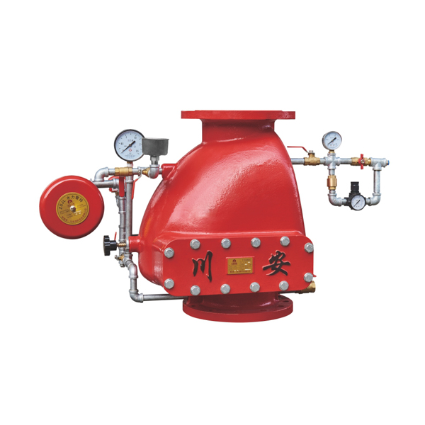
CA-FIRE’s ZSFC Series dry alarm valve is available in DN100, DN150 and DN200 with flanged connections, rated to 1.6 MPa working pressure and compliant with GB 5135.2 and NFPA 13. A pneumatic accelerator is available for all three sizes, reducing water delivery time to the most remote sprinkler head to under 60 seconds — meeting NFPA 13’s mandatory trip time requirement and ensuring that the inherent air-evacuation delay of a dry pipe system does not compromise suppression effectiveness.
Dry Alarm Valve Technical Specifications
[IMAGE: dry alarm valve ZSFC series DN100 DN150 DN200 flanged with accelerator — CA-FIRE] [IMAGE ALT TEXT: dry alarm valve ZSFC series flanged DN100-DN200 pneumatic accelerator — CA-FIRE fire protection]
Dimensional Data
| Nominal Size | Body Height (mm) | Working Pressure | Seal Test | Strength Test | Control Method |
|---|---|---|---|---|---|
| DN100 | 375 | 1.6 MPa | 3.2 MPa | 6.4 MPa | Pneumatic |
| DN150 | 455 | 1.6 MPa | 3.2 MPa | 6.4 MPa | Pneumatic |
| DN200 | 610 | 1.6 MPa | 3.2 MPa | 6.4 MPa | Pneumatic |
Key Parameters
| Parameter | Specification |
|---|---|
| Model | ZSFC 100 / ZSFC 150 / ZSFC 200 |
| Connection | Flanged — ANSI B16.1 / DIN 2501 / GB |
| Working Pressure | 1.6 MPa |
| Seal Test Pressure | 3.2 MPa |
| Strength Test Pressure | 6.4 MPa |
| Supervisory Air Pressure | 0.14–0.28 MPa (20–40 psi) |
| Air-to-Water Pressure Ratio | Approx. 1:6 (differential clapper) |
| Body Material | Ductile cast iron, epoxy coated |
| Clapper Facing | EPDM rubber |
| System Side Medium | Compressed air or dry nitrogen |
| Supply Side Medium | Water |
| System Side Temperature | Below 0°C permitted |
| Supply Side Temperature | Above 4°C required |
| Installation Orientation | Upright (vertical) |
| Alarm Port | G3/4 thread |
| Standards | GB 5135.2, NFPA 13 |
Accelerator Specifications
| Parameter | Specification |
|---|---|
| Compatible Models | ZSFC 100 / 150 / 200 |
| Operating Pressure Range | 0.14–0.55 MPa |
| Trip Pressure Drop | ~0.014–0.028 MPa below setpoint |
| Connection | Threaded, to system air side |
| Function | Rapid differential chamber vent — trips clapper before full air pressure loss |
The Accelerator — Critical Component for NFPA 13 Compliance
[IMAGE: dry alarm valve accelerator pneumatic quick opening device — CA-FIRE ZSFC] [IMAGE ALT TEXT: dry alarm valve pneumatic accelerator quick opening device ZSFC — CA-FIRE]
The single most important performance factor in a dry pipe system is water delivery time — the elapsed time between sprinkler head activation and water reaching the open head. Without an accelerator, a dry pipe system must vent all the compressed air in the distribution network through the open sprinkler orifice before the dry alarm valve trips and water enters the pipework. On any system of practical size, this can take 90 seconds or longer — far exceeding the 60-second maximum permitted by NFPA 13.
The pneumatic accelerator solves this problem. It monitors the supervisory air pressure continuously and, the moment it detects the initial pressure drop caused by a sprinkler head opening, it rapidly vents the intermediate chamber between the dry alarm valve clapper’s air side and water side. This forces the clapper open almost immediately — well before the main air mass in the distribution pipework has finished venting. Water enters the system within seconds of the accelerator tripping, rather than waiting for complete air evacuation.
The result: water delivery time drops from a potentially non-compliant 90+ seconds to well under the 60-second NFPA 13 limit — on every system activation, at every ambient temperature within the design range.
For dry pipe systems protecting cold stores, refrigerated warehouses and large unheated facilities where rapid fire suppression is essential, the accelerator is not optional — it is the component that makes the dry alarm valve system functionally comparable to a wet pipe system in terms of response time, despite the fundamental constraint of having air in the distribution pipework.
CA-FIRE supplies the pneumatic accelerator as a matched accessory for the ZSFC dry alarm valve, factory-calibrated and tested as a complete assembly before despatch.
How the Dry Alarm Valve Works
Standby condition: The dry alarm valve clapper is held shut by compressed air or nitrogen pressure on the system side of the valve. The differential clapper design allows a modest air pressure — typically 0.14–0.28 MPa — to hold back the full water supply pressure on the inlet side, at an approximate ratio of 1:6 (air pressure to water pressure). Both the air-side gauge and water-side gauge are monitored continuously. A low-air pressure alarm switch signals the fire alarm panel if supervisory pressure drops below the minimum setpoint, indicating a distribution system leak.
Sprinkler head activation: When a fire causes a sprinkler head to open, compressed air begins venting through the open orifice. Air pressure on the system side drops. The pneumatic accelerator detects this pressure drop within seconds and vents the differential chamber, causing the dry alarm valve clapper to trip open rapidly. Water from the supply main floods into the distribution pipework and travels toward the open head.
Alarm signal generation: As the clapper lifts, water enters the alarm port and flows through the retard chamber to the water motor alarm gong — producing a mechanical audible alarm without any electrical power — and simultaneously pressurises the pressure switch to send an electrical signal to the fire alarm control panel. Both alarm outputs activate the moment the dry alarm valve trips, providing early warning to occupants and the fire control room before water reaches the open head.
Water delivery: Water travels through the now air-free distribution pipework to the open sprinkler head and discharges onto the fire. With the accelerator installed, this process completes within the NFPA 13 60-second requirement.
Reset: After the fire event, close the supply isolation valve, open the main drain, allow full system drainage, manually reset the dry alarm valve clapper, inspect and replace any activated sprinkler heads, recharge the distribution system with dry compressed air or nitrogen to supervisory pressure, then slowly reopen the supply valve to return to standby.
Complete Dry Alarm Valve Station — Standard Components
A complete ZSFC dry alarm valve station includes the following components, which CA-FIRE can supply as a matched assembly:
Dry alarm valve body (ZSFC) in the specified nominal diameter, with differential pressure clapper and EPDM rubber facing.
Pneumatic accelerator — factory-calibrated for the system supervisory pressure, mounted on the system (air) side of the dry alarm valve. Required for NFPA 13 water delivery time compliance on all but the smallest systems.
Air pressure maintenance device — automatically compensates for minor air leakage from distribution system joints, maintaining supervisory pressure without manual intervention. Prevents spurious low-air alarms from slow leaks.
Retard chamber — delays the alarm signal by 5–30 seconds, absorbing minor air pressure fluctuations that could otherwise cause false activations at the water motor gong and pressure switch.
Water motor alarm gong — mechanical bell driven by water flow through the alarm port. Operates without electrical power. Mounted for maximum audibility throughout the protected zone.
Pressure switch — converts the water pressure signal in the alarm line to an electrical output for the fire alarm control panel. DC 24V / 0.5A.
Low-air pressure alarm switch — monitors supervisory air pressure and signals the fire alarm panel if pressure drops below the minimum setpoint, indicating a distribution system leak before the dry alarm valve trips.
Air and water pressure gauges — separate gauges on the system side (air) and supply side (water) for continuous standby monitoring. A loss of differential between the two gauges indicates an abnormal condition requiring investigation.
Upstream isolation valve — signal gate valve or OS&Y gate valve in the supervised-open position immediately upstream of the dry alarm valve, per NFPA 25 supervisory requirements.
Main drain valve and inspector’s test connection — for annual trip testing and quarterly partial flow tests per NFPA 25.
Dry Alarm Valve vs. Wet Alarm Valve vs. Pre-Action Device
| Dry Alarm Valve | Wet Alarm Valve | Pre-Action Device | |
|---|---|---|---|
| Downstream pipework | Air / nitrogen | Water | Supervisory air |
| Suitable for freezing environments | ✓ Yes | No — pipe will freeze | ✓ Yes |
| Response speed | Requires accelerator for <60s | ✓ Immediate | Requires detection signal + head |
| Accidental discharge protection | Low — any single head trips | Low — any single head trips | ✓ High — dual interlock |
| System complexity | Moderate | ✓ Simplest | Most complex |
| Maintenance burden | Higher — air system requires monitoring | ✓ Lowest | Highest |
| Best application | Freeze-risk environments | Standard buildings above 4°C | Sensitive areas: data centres, archives |
Specify the dry alarm valve for any environment where pipework is exposed to freezing temperatures and double-interlock accidental discharge protection is not required — unheated warehouses, cold stores, parking garages, loading docks, roof spaces and outdoor canopy areas.
Specify the pre-action alarm device when you need both freeze protection AND protection against accidental water discharge — for example, refrigerated data centre facilities or cold storage protecting high-value contents where a pipe failure causing accidental system trip would be as damaging as a fire.
Specify the wet alarm valve for standard indoor building environments where temperatures are consistently maintained above 4°C.
Applications
[IMAGE: dry alarm valve installed cold storage warehouse freezer fire protection — CA-FIRE ZSFC] [IMAGE ALT TEXT: dry alarm valve installed cold storage freezer warehouse fire protection dry pipe system — CA-FIRE]
Cold Storage and Refrigerated Warehouses
Cold-chain logistics facilities, blast-freeze warehouses and refrigerated distribution centres operate at temperatures ranging from −18°C to −30°C. A wet pipe sprinkler system in these environments would freeze solid within hours, rendering the system permanently inoperable. The dry alarm valve — with dry nitrogen preferred over compressed air to minimise internal pipe corrosion — is the only viable automatic sprinkler solution for these facilities. CA-FIRE’s ZSFC series with pneumatic accelerator is regularly specified for large-scale cold chain logistics projects throughout Asia and the Middle East.
Unheated Warehouses and Logistics Facilities
Large logistics warehouses typically include unheated sections — loading dock canopies, external transit areas, staging zones — that are exposed to sub-zero winter temperatures. These areas require dry pipe protection. The ZSFC dry alarm valve covers these zones while the building’s main wet pipe system (using flanged wet alarm valves) serves the heated interior, with the two systems operating independently from their respective riser stations.
Multi-Storey and Underground Parking Garages
Open-deck and partially enclosed parking structures in cold climates experience ambient temperatures well below freezing throughout winter months. Dry pipe systems with ZSFC alarm valves protect these facilities without the freeze-induced system failures that would occur with wet pipe construction. The DN100 and DN150 sizes cover the typical flow demands of parking structure sprinkler zones.
Unheated Industrial Buildings and Warehouses
Manufacturing facilities, steel mills, processing plants and heavy industrial buildings with unheated sections — particularly roof spaces above heated production areas — require dry pipe protection for the exposed zones. The ZSFC series handles the full range of industrial pipe sizes from DN100 through DN200.
Building Roof Spaces and Attics
Where code requires sprinkler protection in unconditioned attic or roof void spaces above occupied building floors, a dry pipe branch fed from a ZSFC dry alarm valve in the heated floor below provides freeze-protected coverage without requiring the roof space to be heated to sprinkler system operating temperatures.
Loading Docks and External Canopy Areas
Covered loading dock areas and external canopy structures attached to otherwise heated buildings are a common location for dry pipe branch systems. The ZSFC dry alarm valve serves these external zones from a valve station inside the heated building envelope, keeping all valve components above freezing while extending dry pipe protection to the exposed areas.
Installation Guidelines
Valve Location
The dry alarm valve body, alarm accessories, air pressure maintenance equipment and all water-side components must be installed inside a heated enclosure — a dedicated fire valve room, mechanical room or heated cabinet — where the ambient temperature will not fall below 4°C under any operating condition. Only the downstream distribution pipework extends into the cold zone. This is a fundamental design requirement of dry pipe systems and is non-negotiable: a frozen dry alarm valve will not trip in a fire.
Air Supply
Charge the distribution system with clean, dry compressed air or dry nitrogen. Moisture in the air supply will condense and freeze inside distribution pipework in cold zones, blocking flow paths and causing premature pipe corrosion. An air dryer upstream of the distribution system connection is recommended for all cold-store applications. Dry nitrogen from a cylinder supply is the preferred medium for cold-store and blast-freeze applications as it eliminates both moisture and oxygen from the system side, dramatically reducing internal pipe corrosion.
Maintain supervisory pressure at 0.14–0.28 MPa (20–40 psi). The air pressure maintenance device compensates for minor leakage automatically. If the maintenance device is running continuously to maintain pressure, a significant system leak exists and requires investigation.
Accelerator Mounting and Calibration
Mount the accelerator on the system (air) side of the dry alarm valve as close to the valve as practicable. Set the trip point at 0.014–0.028 MPa (2–4 psi) below the system supervisory pressure setpoint. Test the accelerator independently before full system commissioning — the accelerator trip point must be lower than the low-air alarm setpoint, and the low-air alarm setpoint must be lower than the dry alarm valve trip pressure, to ensure the correct sequence of events during a fire activation.
Pipework Drainage Gradient
Dry pipe distribution pipework must be installed to a drainage gradient — minimum 25 mm per 3 m (1 inch per 10 feet) for pipes 65 mm and larger — so that residual water remaining after a system activation drains back to the main drain connection. Water standing in distribution pipework will freeze in cold-zone installations, permanently blocking the system.
Maximum System Volume
Per NFPA 13, a single dry alarm valve may protect a maximum system volume of approximately 2,840 litres (750 US gallons). Large cold stores or warehouses requiring greater system volume must use multiple dry alarm valve stations. CA-FIRE’s engineering team can advise on multi-valve zone configurations for large-scale projects.
Maintenance Schedule
Dry pipe systems require more frequent inspection and testing than wet pipe systems due to the additional complexity of air pressure supervision. Per NFPA 25:
| Frequency | Task |
|---|---|
| Weekly | Visual inspection — air-side and water-side pressure gauges; valve exterior for leaks; confirm air maintenance device is not running continuously |
| Monthly | Verify low-air alarm function — confirm pressure switch signals fire alarm panel at the correct setpoint |
| Quarterly | Partial trip test via inspector’s test connection — verify water motor alarm gong and pressure switch both activate; check retard chamber drain operates correctly |
| Annually | Full trip test — open inspector’s test connection fully, measure and record water delivery time to most remote head, verify accelerator function; full internal inspection of clapper, EPDM facing, seat and alarm port; flush retard chamber; check all flange connections |
| Every 3 years | Full internal inspection of valve body and accelerator; replace EPDM clapper facing; inspect and clean air maintenance device internals |
Frequently Asked Questions
Why does a dry pipe system need an accelerator?
Without an accelerator, the dry alarm valve clapper can only trip after enough compressed air has vented through the open sprinkler head to reduce system air pressure below the differential trip point. On any system of practical size, this takes longer than the 60-second NFPA 13 water delivery time limit. The accelerator detects the initial pressure drop and trips the clapper mechanically — well before the main air mass has finished venting — reducing water delivery time to well under 60 seconds. For NFPA 13 compliance on all but the very smallest dry pipe systems, the accelerator is essential.
Can nitrogen be used instead of compressed air?
Yes, and it is often preferred. Dry nitrogen eliminates both moisture and oxygen from the distribution system, preventing the oxygen-driven internal corrosion of steel pipe that is a known long-term reliability issue with air-charged dry pipe systems. Nitrogen also requires no air dryer and is available in cylinder supply for smaller systems. For large cold-store facilities with extensive distribution pipework, nitrogen inerting significantly extends the service life of the system piping.
Where must the dry alarm valve be located?
The dry alarm valve and all alarm accessories, gauges and water-side piping must be installed in a heated location — a valve room, mechanical room or heated cabinet — where the temperature will not fall below 4°C. Only the downstream distribution pipework extends into the cold zone. A dry alarm valve installed in an unheated location will freeze, fail to trip in a fire, and may be physically damaged by ice formation in the water-side chamber.
How often must the full trip test be conducted?
NFPA 25 requires an annual full operational trip test of the dry alarm valve, during which the valve is tripped, water delivery time to the most remote test connection is measured and recorded, and the clapper is inspected internally. The trip test is the most important maintenance activity for a dry pipe system — it is the only way to verify that water delivery time remains within the NFPA 13 60-second limit and that the accelerator is functioning correctly.
What is the maximum size system a single ZSFC dry alarm valve can serve?
Per NFPA 13, a single dry pipe valve station may serve a maximum system volume of approximately 2,840 litres (750 US gallons) for standard installations. For larger systems, multiple dry alarm valve stations are required, each serving a separate zone. CA-FIRE’s engineering team can assist with zone configuration design for large cold stores or warehouses exceeding this volume limit.
Get a Quote
Contact CA-FIRE for pricing, complete dry alarm valve station assemblies, accelerator specifications, technical drawings or OEM supply enquiries. Our engineering team responds within one business day.
- Email: sales@ca-fire.com
- Mobile: +86 13400715622 | WhatsApp: +86 18150362095
- WeChat: 404863577
- Website: www.ca-fire.com
Related products: Wet Alarm Valve — Flanged · Pre-Action Alarm Device · Stainless Steel Alarm Valve · Grooved Alarm Valve · Signal Gate Valve · Alarm Check Valve Series
For dry pipe system design, installation and maintenance requirements, refer to NFPA 13 (Standard for the Installation of Sprinkler Systems) and NFPA 25 (Inspection, Testing and Maintenance of Water-Based Fire Protection Systems).
Available Sizes and Dimensions
| Size (DN) | Height (mm) | Working Pressure | Seal Test Pressure | Strength Test Pressure | Control Method |
|---|---|---|---|---|---|
| DN100 | 375 mm | 1.6 MPa | 3.2 MPa | 6.4 MPa | Pneumatic |
| DN150 | 455 mm | 1.6 MPa | 3.2 MPa | 6.4 MPa | Pneumatic |
| DN200 | 610 mm | 1.6 MPa | 3.2 MPa | 6.4 MPa | Pneumatic |
Key Technical Parameters
| Parameter | Value |
|---|---|
| Product Model | ZSFC 100/150/200 |
| Connection Type | Flanged |
| Nominal Working Pressure | 1.6 MPa (16 bar / 232 psi) |
| Seal Test Pressure | 3.2 MPa |
| Strength Test Pressure | 6.4 MPa |
| Control Method | Pneumatic (Air / Nitrogen) |
| Supervisory Air Pressure | Typically 0.14–0.28 MPa (20–40 psi) |
| Valve Body Material | Ductile Cast Iron, Epoxy Coated |
| Clapper Facing Material | EPDM Rubber |
| Applicable Medium | Water (supply side); Air / Nitrogen (system side) |
| Applicable Temperature | System side: below 0°C permitted; Supply side: above 4°C |
| Installation Orientation | Horizontal or vertical per model |
| Alarm Port Size | G3/4 thread |