
Wet Alarm Valve — Flanged ZSFZ Series for Wet Pipe Sprinkler Systems
A wet alarm valve is the central control component of a wet pipe automatic sprinkler system. Installed on the system riser between the water supply and the sprinkler distribution pipework, it holds the entire downstream network at supply pressure, prevents backflow into the water main, and automatically detects the moment a sprinkler head opens — triggering the water motor alarm gong and pressure switch signal to the fire alarm control panel within seconds, without any electrical power required for the alarm initiation itself.
CA-FIRE’s ZSFZ Series flanged wet alarm valve is manufactured from epoxy-coated ductile iron in eight nominal sizes from DN65 to DN300, covering every wet pipe sprinkler system application from small commercial installations through to large industrial and high-rise building primary risers. Each valve is factory tested to 6.4 MPa strength and 3.2 MPa seal before despatch, and is designed in compliance with GB 5135.1 and NFPA 13 requirements for wet alarm valve performance.
Wet Alarm Valve Technical Specifications
[IMAGE: wet alarm valve flanged ZSFZ series ductile iron DN65-DN300 — CA-FIRE] [IMAGE ALT TEXT: wet alarm valve flanged ZSFZ series DN65-DN300 ductile iron fire sprinkler — CA-FIRE]
Dimensional Data
| Nominal Size | Body Height (mm) | Working Pressure | Seal Test | Strength Test | Friction Loss |
|---|---|---|---|---|---|
| DN65 | 200 | 1.6 MPa | 3.2 MPa | 6.4 MPa | < 0.02 MPa |
| DN80 | 230 | 1.6 MPa | 3.2 MPa | 6.4 MPa | < 0.02 MPa |
| DN100 | 260 | 1.6 MPa | 3.2 MPa | 6.4 MPa | < 0.02 MPa |
| DN125 | 275 | 1.6 MPa | 3.2 MPa | 6.4 MPa | < 0.02 MPa |
| DN150 | 305 | 1.6 MPa | 3.2 MPa | 6.4 MPa | < 0.02 MPa |
| DN200 | 375 | 1.6 MPa | 3.2 MPa | 6.4 MPa | < 0.02 MPa |
| DN250 | 470 | 1.6 MPa | 3.2 MPa | 6.4 MPa | < 0.02 MPa |
| DN300 | 560 | 1.6 MPa | 3.2 MPa | 6.4 MPa | < 0.02 MPa |
Key Parameters
| Parameter | Specification |
|---|---|
| Model | ZSFZ 65–300-1.6 |
| Connection | Flanged — ANSI B16.1 / DIN 2501 / GB |
| Working Pressure | 1.6 MPa |
| Seal Test Pressure | 3.2 MPa |
| Strength Test Pressure | 6.4 MPa |
| Hydraulic Friction Loss | < 0.02 MPa |
| Body Material | Ductile cast iron (GGG50), epoxy coated |
| Clapper Material | Ductile iron with EPDM rubber facing |
| Medium | Water |
| Temperature Range | 4–70 °C |
| Installation Orientation | Upright (vertical) — flow upward |
| Alarm Port | G3/4 thread |
| Standards | GB 5135.1, NFPA 13 |
How the Wet Alarm Valve Works
Understanding the wet alarm valve operating cycle helps engineers specify the correct accessory configuration and ensures maintenance personnel can identify correct and abnormal system behaviour during inspections.
Standby condition: The wet alarm valve clapper sits on its seat under the weight of the water column above it and the balanced pressure across both sides of the clapper. Both the supply-side and system-side pressure gauges show equal pressure — typically the supply main pressure. The alarm port is closed. No water flows.
Sprinkler head activation: When a sprinkler head opens in response to heat, water discharges from the open head. Downstream pressure drops. The pressure differential across the wet alarm valve clapper lifts it off its seat, allowing water to flow freely from the supply main through the valve and into the distribution pipework toward the open head.
Alarm signal generation: As the clapper lifts, water enters the alarm port and flows through the retard chamber into the alarm line. The retard chamber — a small accumulator vessel — absorbs brief pressure fluctuations from supply pressure surges, preventing false alarms. When sustained flow confirms a genuine activation, water drives the water motor alarm gong to produce a mechanical audible alarm, and simultaneously pressurises the pressure switch to send an electrical signal to the fire alarm control panel.
Restoration: After fire suppression, the water supply is isolated, operated sprinkler heads are replaced, the system is drained, refilled and repressurisied. The wet alarm valve clapper reseats under restored supply pressure and the system returns to standby.
Wet Alarm Valve Assembly — Standard Components
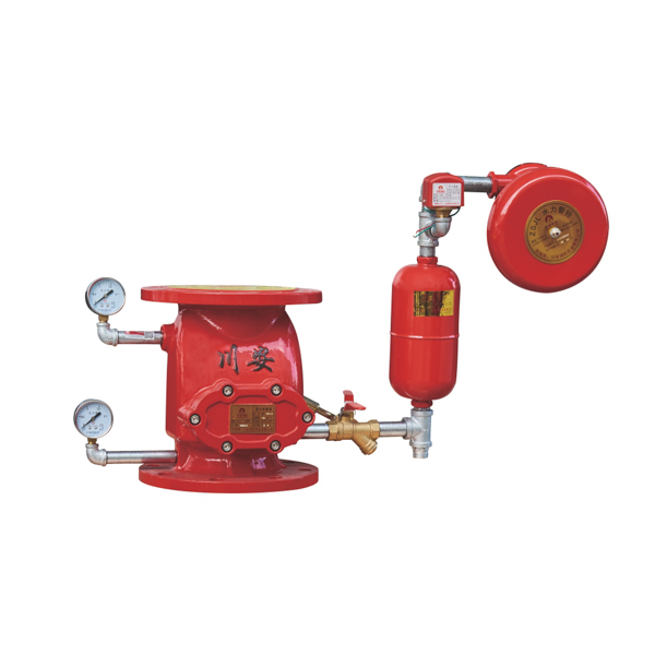
[IMAGE: wet alarm valve assembly complete station water motor gong retard chamber — CA-FIRE ZSFZ] [IMAGE ALT TEXT: wet alarm valve assembly complete station with water motor gong retard chamber pressure switch — CA-FIRE]
The wet alarm valve is supplied and installed as part of a complete wet alarm valve assembly station. CA-FIRE supplies all components as a matched set:
Core valve: ZSFZ flanged wet alarm valve in the specified nominal diameter.
Retard chamber: Delays the alarm signal by 5–30 seconds to prevent spurious activations from momentary supply pressure fluctuations. Required on virtually all wet alarm valve installations.
Water motor alarm gong: Mechanically driven by water flow through the alarm port — produces a loud audible alarm without any electrical power. Mounted externally on the building facade or in the valve room for maximum audibility.
Pressure switch: Converts the water pressure signal in the alarm line to an electrical output for connection to the fire alarm control panel. Provides the remote monitoring and system integration capability that the mechanical gong alone cannot.
Upstream and downstream pressure gauges: Continuous monitoring of supply and system pressures during standby. A drop in system pressure relative to supply pressure indicates a leak or partial discharge; equal pressures confirm the valve is correctly seated.
Test and drain valve: Allows periodic alarm testing via the inspector’s test connection without fully tripping the system, and provides system drainage after shutdown.
Upstream isolation valve: A signal gate valve or OS&Y gate valve installed immediately upstream of the wet alarm valve, providing supervised isolation for maintenance without removing the water supply to the whole building.
Key Features
Low Hydraulic Friction Loss — < 0.02 MPa
The ZSFZ wet alarm valve body profile is designed to minimise hydraulic resistance across the valve in the open (flowing) position. At less than 0.02 MPa, the friction loss across the wet alarm valve is lower than many equivalent products on the market — reducing the hydraulic head loss budget consumed by the valve station and allowing more head to be available for the sprinkler system hydraulic design. In large systems where every 0.01 MPa of friction loss at the alarm valve station affects the number of sprinkler heads that can be covered at the design pressure, this low friction loss figure is a meaningful specification advantage.
Ductile Iron Body — Strength and Impact Resistance
The ZSFZ wet alarm valve body is cast from GGG50 ductile iron — the same material standard used for high-quality fire protection valves globally. GGG50 ductile iron provides significantly higher tensile strength and impact resistance than grey cast iron, withstanding the pressure surges and water hammer events that occur in fire protection systems during pump start-up and rapid valve closure without cracking. The epoxy coating applied inside and outside the body provides corrosion protection for the full design service life in standard indoor environments.
EPDM Clapper Facing — Long-Term Sealing Reliability
The clapper sealing face is fitted with EPDM rubber, which maintains elastic sealing properties across the full 4–70 °C operating temperature range without permanent compression set, hardening or cracking. EPDM is chemically compatible with potable and treated fire protection water, does not absorb chlorine or other common water treatment agents, and provides consistent, leak-free seating of the clapper throughout the wet alarm valve’s service life with minimal maintenance intervention.
Flanged Connections — Permanent, High-Integrity Joints
The raised-face flanged inlet and outlet connections of the ZSFZ wet alarm valve create permanent, pressure-tight joints to the pipeline flanges using standard gaskets and bolt sets. Flanged connections are the correct specification for wet alarm valve installations in commercial and industrial buildings — they provide the rigidity and joint integrity needed at the critical alarm valve station location, are fully compatible with all three major flange drilling standards (ANSI B16.1, DIN 2501, GB), and allow the valve to be removed for inspection or replacement without cutting the pipeline.
Wet Alarm Valve vs. Dry Alarm Valve — Key Differences
A common question when specifying fire protection systems is when to use a wet alarm valve versus a dry pipe or pre-action alternative.
| Wet Alarm Valve | Dry Alarm Valve | Pre-Action Device | |
|---|---|---|---|
| Downstream pipework | Water-filled | Air/nitrogen-filled | Dry or supervisory air |
| Response speed | ✓ Fastest — water at head immediately | Slower — air must vent first | Slower — detection + head both required |
| Suitable temperature | Above 4°C consistently | ✓ Freezing environments | ✓ Sensitive environments |
| False discharge risk | Low | Low | ✓ Lowest — double interlock |
| System complexity | ✓ Simplest | Moderate | Most complex |
| Best application | Standard buildings | Cold stores, unheated areas | Data centres, museums, archives |
Specify the wet alarm valve for any building where temperatures remain consistently above 4°C — the vast majority of commercial, institutional and industrial applications. For cold environments, specify the dry alarm valve. For sensitive areas requiring detection confirmation before water admission, specify the pre-action alarm device.
Applications
High-Rise Commercial and Residential Buildings
Office towers, apartment buildings, hotels and mixed-use high-rise developments install wet alarm valves on every sprinkler zone riser — typically one per floor or per fire zone. The wet alarm valve’s simple, reliable operating principle and low maintenance requirement make it the universal specification for multi-storey building wet pipe sprinkler systems worldwide.
Shopping Centres and Retail
Large retail developments with high occupancy loads and significant contents value depend on rapid sprinkler response to contain fires in their early stages. The wet alarm valve’s instantaneous water delivery — water is already at the sprinkler head before activation — minimises fire growth in the critical seconds after a head opens.
Hospitals and Healthcare Facilities
Healthcare facilities require dependable, continuously operational fire protection with minimum false alarm risk. The wet alarm valve’s retard chamber suppresses spurious activations from supply pressure fluctuations, while its simple hydraulic alarm mechanism provides reliable alarm initiation without dependence on electrical power at the valve itself.
Data Centres and Server Rooms (Temperature-Controlled)
In data centres where ambient temperature is consistently maintained above 4°C by the facility’s cooling system, wet pipe sprinkler systems with flanged wet alarm valves are frequently specified for general areas. For IT equipment rooms where accidental discharge risk is unacceptable, the pre-action alarm device is the correct choice.
Warehouses and Logistics Facilities
Heated warehouses and distribution centres protecting combustible stored goods and high-value inventory use wet pipe sprinkler systems as the most cost-effective automatic suppression approach. The ZSFZ wet alarm valve in larger nominal sizes — DN200 to DN300 — handles the high flow demands of large-area warehouse sprinkler systems with low friction loss.
Airports and Transport Infrastructure
Major transport infrastructure projects — airport terminals, metro stations, rail terminals — specify wet alarm valves on large-scale wet pipe sprinkler systems covering passenger concourses, retail zones and baggage handling areas. CA-FIRE’s ZSFZ series has been installed at multiple major Chinese airport and metro projects.
Installation Guidelines
Pre-Installation
- Confirm the wet alarm valve nominal diameter matches the system riser size on the design drawings.
- Verify the flange drilling standard (ANSI/DIN/GB) matches the project pipework flanges.
- Inspect the valve body, clapper and alarm port for transit damage before installation.
- Confirm the installation location provides adequate clearance for alarm accessories, pressure gauges, test connection and future maintenance access — minimum 600 mm clearance recommended on all sides.
Mechanical Installation
Install the wet alarm valve in the upright (vertical) position with the flow direction arrow pointing upward — from supply below to system above. The valve must never be installed on its side or inverted; incorrect orientation prevents the clapper from seating correctly and will cause continuous leakage through the alarm port. Connect the upstream and downstream pipeline flanges with the correct gasket material, torquing all flange bolts evenly in a cross-pattern sequence. Connect the alarm accessories — retard chamber, water motor gong, pressure switch — to the alarm port using the correct tubing and fittings per the manufacturer’s schematic.
Commissioning
After installation, fill the system with water from the supply side, purge air from the system through the inspector’s test connection, and confirm both pressure gauges stabilise at the correct standby pressure. Conduct a full-flow alarm test by opening the inspector’s test connection fully and verifying: clapper opens under flow, water motor alarm gong activates within 90 seconds, pressure switch sends signal to fire alarm panel, and both gauges show correct pressure differential during flow. Record all commissioning test results for the authority inspection record.
Maintenance Schedule
Per NFPA 25 requirements for wet alarm valve inspection, testing and maintenance:
| Frequency | Task |
|---|---|
| Weekly | Visual inspection — both pressure gauges, valve exterior and alarm piping for leaks or physical damage |
| Monthly | Confirm upstream isolation gate valve is fully open and in supervised position |
| Quarterly | Water flow alarm test via inspector’s test connection — verify water motor gong and pressure switch both respond; check retard chamber drain operates correctly |
| Annually | Full internal inspection — remove and inspect clapper, check EPDM facing for hardening or cracking, inspect seat for scale or debris, inspect retard chamber internally, check all flange connections for tightness |
| Every 5 years | Replace EPDM clapper facing as preventive measure, or earlier if annual inspection detects hardening, cracking or compression set |
Frequently Asked Questions
What is the difference between a wet alarm valve and an alarm check valve?
The terms are used interchangeably in practice. An alarm check valve is the broader category name for any one-way valve with an alarm port used in sprinkler systems — covering wet pipe, dry pipe and other types. A wet alarm valve specifically refers to the alarm check valve used in wet pipe systems, where the downstream pipework is filled with water. CA-FIRE’s ZSFZ Series is both a wet alarm valve and an alarm check valve for wet pipe applications.
Does the wet alarm valve require electrical power to operate?
No. The wet alarm valve operates entirely hydraulically — the clapper opens under water pressure differential when a sprinkler head activates, and water flowing through the alarm port drives the water motor alarm gong mechanically without any electrical supply. The pressure switch connected to the alarm port does require electrical power to send its signal to the fire alarm panel, but the alarm valve’s core fire detection and alarm function is independent of the electrical system.
Can the wet alarm valve be installed horizontally?
No. The ZSFZ flanged wet alarm valve must be installed vertically with flow directed upward through the valve. Horizontal or inverted installation prevents the clapper from seating correctly under gravity, causing continuous water leakage through the alarm port and false alarm conditions.
How do I know when the wet alarm valve needs maintenance?
The primary maintenance indicators are the two pressure gauges. During standby, both supply-side and system-side gauges should show equal pressure. A system-side pressure reading lower than supply pressure indicates either a leak in the downstream pipework or that the wet alarm valve clapper is not fully seated — both warrant immediate investigation. A sudden alarm activation without any fire event should prompt inspection of the retard chamber and clapper seat for debris or damage.
What is the correct upstream isolation valve to use with a wet alarm valve?
NFPA 25 requires that the control valve upstream of the wet alarm valve be of a supervised type — either a signal gate valve with a tamper switch, an OS&Y gate valve with a tamper switch, or a signal butterfly valve. CA-FIRE’s signal gate valve and OS&Y gate valve series are directly compatible with the ZSFZ wet alarm valve installation and meet NFPA 25 supervisory requirements.
Get a Quote
Contact CA-FIRE for pricing, complete alarm valve station assemblies, technical drawings or OEM supply enquiries. Our engineering team responds within one business day.
- Email: sales@ca-fire.com
- Mobile: +86 13400715622 | WhatsApp: +86 18150362095
- WeChat: 404863577
- Website: www.ca-fire.com
Related products: Stainless Steel Alarm Valve · Grooved Alarm Valve · Dry Alarm Valve · Pre-Action Alarm Device · Signal Gate Valve · Alarm Check Valve Series
For wet alarm valve installation, testing and maintenance requirements, refer to NFPA 13 (Standard for the Installation of Sprinkler Systems) and NFPA 25 (Inspection, Testing and Maintenance of Water-Based Fire Protection Systems).
| Size (DN) | Height (mm) | Working Pressure | Seal Test Pressure | Strength Test Pressure | Hydraulic Friction Loss |
|---|---|---|---|---|---|
| DN65 | 200 mm | 1.6 MPa | 3.2 MPa | 6.4 MPa | < 0.02 MPa |
| DN80 | 230 mm | 1.6 MPa | 3.2 MPa | 6.4 MPa | < 0.02 MPa |
| DN100 | 260 mm | 1.6 MPa | 3.2 MPa | 6.4 MPa | < 0.02 MPa |
| DN125 | 275 mm | 1.6 MPa | 3.2 MPa | 6.4 MPa | < 0.02 MPa |
| DN150 | 305 mm | 1.6 MPa | 3.2 MPa | 6.4 MPa | < 0.02 MPa |
| DN200 | 375 mm | 1.6 MPa | 3.2 MPa | 6.4 MPa | < 0.02 MPa |
| DN250 | 470 mm | 1.6 MPa | 3.2 MPa | 6.4 MPa | < 0.02 MPa |
| DN300 | 560 mm | 1.6 MPa | 3.2 MPa | 6.4 MPa | < 0.02 MPa |
Key Technical Parameters
| Parameter | Value |
|---|---|
| Product Model | ZSFZ 80~300-1.6 |
| Connection Type | Flanged |
| Nominal Working Pressure | 1.6 MPa (16 bar) |
| Seal Test Pressure | 3.2 MPa |
| Strength Test Pressure | 6.4 MPa |
| Hydraulic Friction Loss | < 0.02 MPa |
| Valve Body Material | Ductile Cast Iron (Epoxy Coated) |
| Clapper Material | Ductile Iron with EPDM Rubber Facing |
| Applicable Medium | Water |
| Applicable Temperature Range | 4°C to 70°C |
| Installation Orientation | Upright (vertical) |
| Alarm Port | 20 mm (G3/4 thread for alarm accessories) |